Assessment of multiple mission reusable launch vehicles (original) (raw)
Abstract
Multiple mission reusable launch vehicles could be an interesting and attractive option of the future with cost saving potential. A similar RLV-configuration capable of fulfilling very different needs might significantly reduce the development effort compared to individual developments of several dedicated crafts. The announcement of Elon Musk on the imminent development of a fully reusable two-stage launcher to LEO of very large size, called "BFR" is one spectacular example. DLR's SpaceLiner concept is similar in certain aspects to the idea of multiple mission reusable launch vehicles. While in its primary role conceived as an ultrafast intercontinental passenger transport, in its second role the SpaceLiner is intended as an RLV capable of delivering heavy payloads into orbit. The paper provides multidisciplinary technical analyses of the different proposed multi-mission RLV-concepts. The characteristic flight conditions of winged gliding stages with those of rocket-decelerated vertical landing vehicles are compared. Performance, size and safety aspects are evaluated.
Key takeaways
![]()
AI
- BFR aims for a payload capacity of 150 tons to Low Earth Orbit (LEO).
- SpaceLiner's design allows for ultrafast intercontinental travel with a focus on cost efficiency.
- Both vehicles utilize reusable stages, enhancing economic viability in space transport.
- BFR uses liquid oxygen and liquid methane, while SpaceLiner employs liquid oxygen and liquid hydrogen as propellants.
- Cost estimates suggest SpaceLiner could achieve launch costs below €2000/kg for GTO missions.
Figures (37)
![Figure 1: BFR 2017 rocket-propelled intercontinental passenger transport in vertical landing mode from SpaceX video animation [2] Figure 2: The SpaceLiner rocket-propelled inter- continental passenger transport in final horizontal landing approach](https://figures.academia-assets.com/70046141/figure_001.jpg) ](
](Figure 1: BFR 2017 rocket-propelled intercontinental passenger transport in vertical landing mode from SpaceX video animation [2] Figure 2: The SpaceLiner rocket-propelled inter- continental passenger transport in final horizontal landing approach
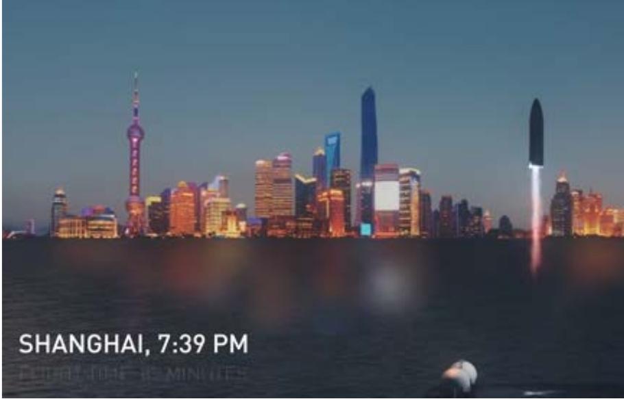
The probably most spectacular application of the multiple mission reusable launch vehicles which also could generate most of the commercial revenue is the role as ultrafast intercontinental passenger transport. Both example concepts of this paper use vertical launch like all rockets, however, Figure 1 and Figure 2 sum- marize in a graphical representation the key difference in selected landing modes. BFR is announced to have also vertical landing using its main propulsion system (Figure 1) while the SpaceLiner has been designed for horizontal touch-down on a runway after its hypersonic reentry gliding (Figure 2).
![Figure 3: Artists impression of satellite payload release from BFS’ open payload bay in LEO [3]](https://figures.academia-assets.com/70046141/figure_003.jpg) ](
](Figure 3: Artists impression of satellite payload release from BFS’ open payload bay in LEO [3]
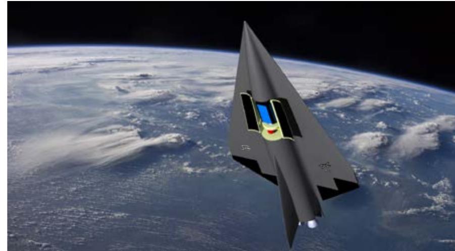
Figure 4: Artists impression of satellite payload release from SpaceLiner 7 Orbiter’s open payload bay in LEO
![Figure 5: Artists impression of BFS 2017 at futuristic Martian spaceport [3]](https://figures.academia-assets.com/70046141/figure_005.jpg) ](
](Figure 5: Artists impression of BFS 2017 at futuristic Martian spaceport [3]
![Figure 6: Drawing of BFR launch configuration with passenger stage on the right and booster stage on the left [3] At the end of 2012 with conclusion of FAST20XX the SpaceLiner 7 reached a consolidated technical status. Another important milestone has been achieved in 2016](https://figures.academia-assets.com/70046141/figure_006.jpg) ](
](Figure 6: Drawing of BFR launch configuration with passenger stage on the right and booster stage on the left [3] At the end of 2012 with conclusion of FAST20XX the SpaceLiner 7 reached a consolidated technical status. Another important milestone has been achieved in 2016
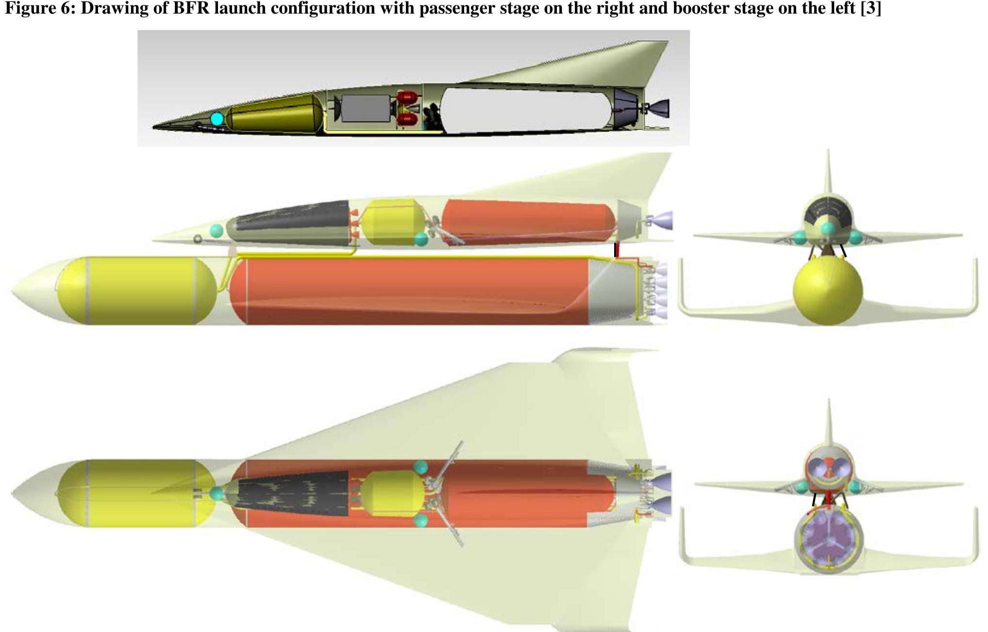
Figure 7: Sketch of SpaceLiner 7 launch configuration with passenger stage (SLP) with its booster stage at bottom position and orbital stage of SLO in insert at top
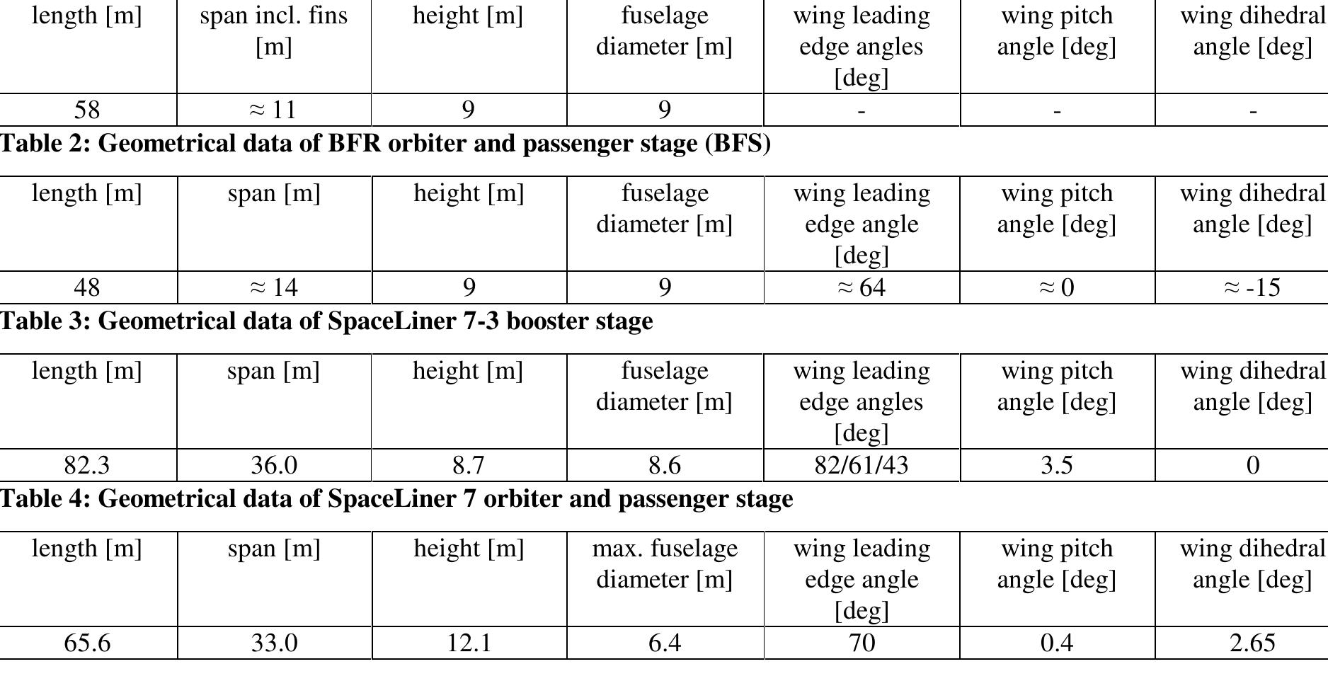
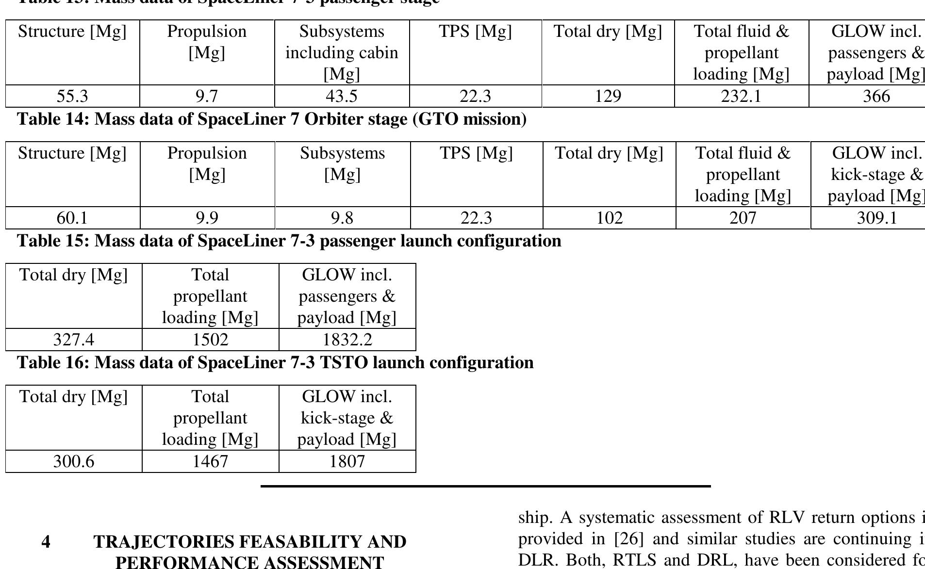
Table 1: Geometrical data of BFR booster stage Total dry mass of the SpaceLiner 7 launch configuration is estimated at 301 Mg (satellite version) and 327 Mg (passenger version) with a total propellant loading of 1467 Mg or 1502 Mg. The resulting GLOWs are 1807 Mg (satellite version) and 1832 Mg (passenger version) either incl. passengers or payload and expendable upper stage.
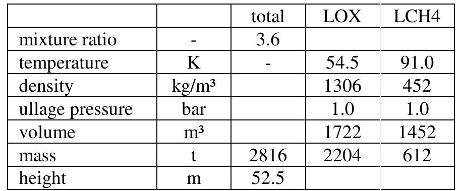
Table 5: Estimated propellant conditions in the BFR booster stage Note that both fluid temperatures are assumed to be very low, close to their freezing points to achieve maximum
lowest possible temperatures very close to the respective freezing points were assumed in the DLR simulation to check on the maximum amount of propellant potentially to be loaded into the tanks. Tank mixture ratio is set to the Raptor engine mixture ratio which is sufficiently accurate for an initial assumption. A sketch of the booster stage’s tank system generated with the DLR tool pmp is presented in Figure 8 and conditions of the loaded propellants are found in Table 5. Figure 8: Sketch of the BFR booster stage tanks as modeled by DLR
![Figure 9 shows the BFS geometry with an ogival nose section, cylindrical fuselage and a relatively small delta wing inclined that the lower side builds a flat surface with the fuselage. The chord thickness at the root is high and the airfoil is wedge-like without sharp trailing edge. This feature indicates that the wing is not intended to be used in low-speed and subsonic flight. Figure 9: Drawings of BFR passenger stage or BFS in side and aft view [1, 3]](https://figures.academia-assets.com/70046141/figure_009.jpg) ](
](Figure 9 shows the BFS geometry with an ogival nose section, cylindrical fuselage and a relatively small delta wing inclined that the lower side builds a flat surface with the fuselage. The chord thickness at the root is high and the airfoil is wedge-like without sharp trailing edge. This feature indicates that the wing is not intended to be used in low-speed and subsonic flight. Figure 9: Drawings of BFR passenger stage or BFS in side and aft view [1, 3]
![The passenger stage contains two main tanks and two header tanks (Figure 12). The main tanks contain the propellant for the ascent, the header tanks the propellant for the return to Earth. [1] The header tanks are fully immersed in the main LCH4-tank. Figure 12: Drawing of BFS highlighting tank and engine sections [3]](https://figures.academia-assets.com/70046141/figure_010.jpg) ](
](The passenger stage contains two main tanks and two header tanks (Figure 12). The main tanks contain the propellant for the ascent, the header tanks the propellant for the return to Earth. [1] The header tanks are fully immersed in the main LCH4-tank. Figure 12: Drawing of BFS highlighting tank and engine sections [3]
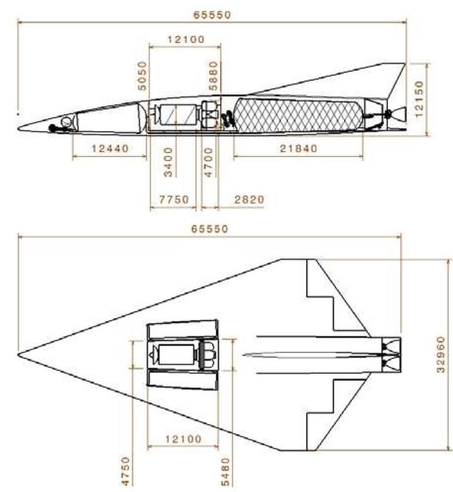
![Figure 11: Drawing of BFS in passenger configura- tion showing internal sections [3]](https://figures.academia-assets.com/70046141/figure_011.jpg) ](
](Figure 11: Drawing of BFS in passenger configura- tion showing internal sections [3]
![intrimmed flight configuration as the dimensions of the BFS trimming devices are unknown. According to [1] he delta wing also includes a split flap for pitch and roll control, which should allow “to control the pitch angle for a wide range of payloads in the forward nose and a wide range of atmospheric densities”.](https://figures.academia-assets.com/70046141/figure_012.jpg) ](
](intrimmed flight configuration as the dimensions of the BFS trimming devices are unknown. According to [1] he delta wing also includes a split flap for pitch and roll control, which should allow “to control the pitch angle for a wide range of payloads in the forward nose and a wide range of atmospheric densities”.
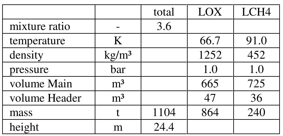
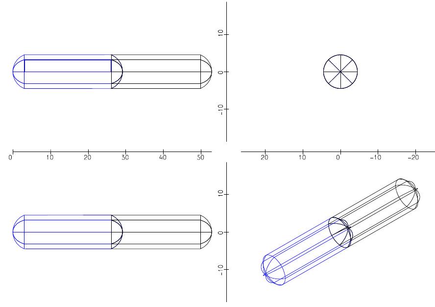
Table 6: Estimated propellant conditions in the BFR’s passenger stage
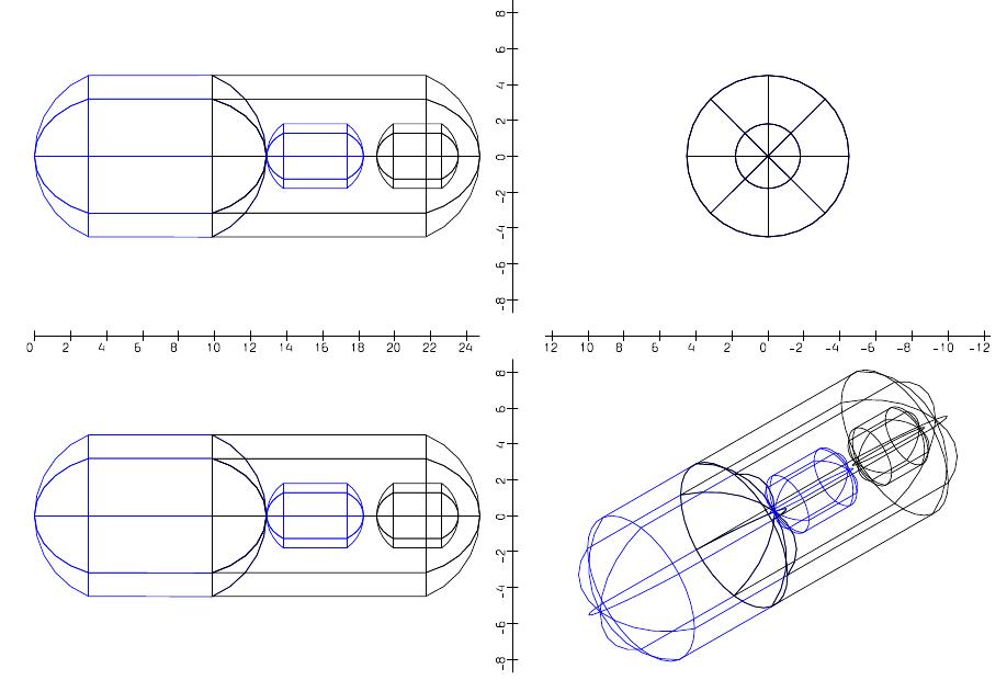
According to reference 1 the BFS stage is expected to carry 240 tons of methane and 860 tons of oxygen. Based on this information and using Figure 12 DLR calculated the BFS tank system. As visible in Figure 13 and Table 6, the intended propellant loading of 1100 tons fits in the available length. While LCH4 is again subcooled close to its freezing point, the temperature of subcooled LOX could be kept above 66 K in the BFS. Figure 13: Sketch of the BFR passenger stage tanks as modeled by DLR
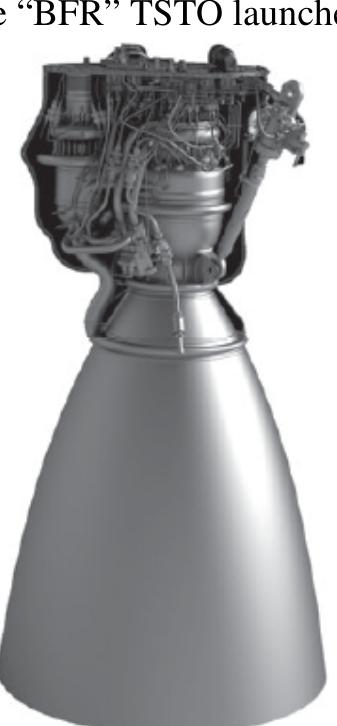
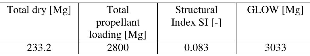
Table 8: DLR estimated mass data of BFR booster stage Table 9: DLR estimated mass data of BFR passenger stage
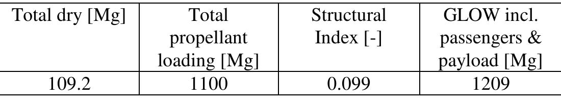
Table 10: DLR estimated mass data of BFR passenger launch configuration
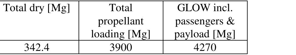
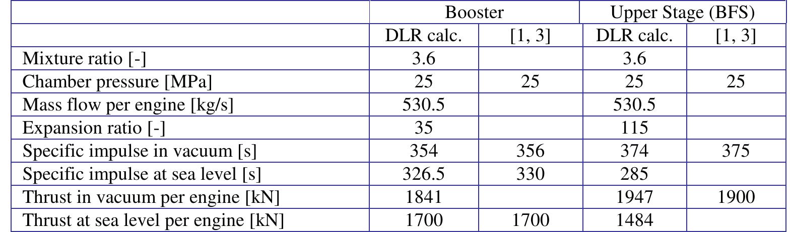
Table 7: BFR Main Engine (Raptor) technical data
![Figure 16: SpaceLiner 7-3 passenger stage The SpaceLiner7 aerodynamic shape is a result of a trade-off between the optima of three reference trajectory points and showed considerable improvements in glide ratio and heat loads compared with previous designs and pointed out the clear advantages of a single delta wing [14]. Major geometry data of the SpaceLiner 7-3 passenger and orbiter stage are summarized in Table 4. The SpaceLiner passenger stage’s shape is shown in Figure 16.](https://figures.academia-assets.com/70046141/figure_015.jpg) ](
](Figure 16: SpaceLiner 7-3 passenger stage The SpaceLiner7 aerodynamic shape is a result of a trade-off between the optima of three reference trajectory points and showed considerable improvements in glide ratio and heat loads compared with previous designs and pointed out the clear advantages of a single delta wing [14]. Major geometry data of the SpaceLiner 7-3 passenger and orbiter stage are summarized in Table 4. The SpaceLiner passenger stage’s shape is shown in Figure 16.
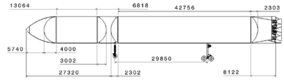
Figure 15; Sketch of SpaceLiner 7 booster stage intertank and the thrust frame. Further, the size of the body flap and the geometry of the large wing were optimized. Major geometrical data of this configuration 7-3 are listed in Table 3.
cabin related masses. Instead a mass provision for the payload bay and its mechanisms including doors, the mounting structure, and also a radiator system for on- orbit heat-control is added. The resulting orbiter dry mass is about 102 Mg and the budget is listed in Table 14. Figure 17: Sketch of SpaceLiner 7 as orbital space transportation with internal cargo bay for satellites
![Table 11: SpaceLiner Main Engine (SLME) technical data [13, 20] subsystems being the separation motors, the thermal protection system (TPS), and the structure. These three subsystems have been investigated and sized for function, performance, and mass [17, 25, 27, 28]. The size of the SLME in the smaller booster configuration is a maximum diameter of 1800 mm and overall length of 2981 mm. The larger passenger stage SLME has a maximum diameter of 2370 mm and overall length of 3893 mm. A size comparison of the two variants and overall arrangement of the engine components is visible in Figure 18. All engines have a 2D TVC (thrust vector control) capability with gimbal mechanism which should be electro-mechanically actuated.](https://figures.academia-assets.com/70046141/table_008.jpg) ](
](Table 11: SpaceLiner Main Engine (SLME) technical data [13, 20] subsystems being the separation motors, the thermal protection system (TPS), and the structure. These three subsystems have been investigated and sized for function, performance, and mass [17, 25, 27, 28]. The size of the SLME in the smaller booster configuration is a maximum diameter of 1800 mm and overall length of 2981 mm. The larger passenger stage SLME has a maximum diameter of 2370 mm and overall length of 3893 mm. A size comparison of the two variants and overall arrangement of the engine components is visible in Figure 18. All engines have a 2D TVC (thrust vector control) capability with gimbal mechanism which should be electro-mechanically actuated.
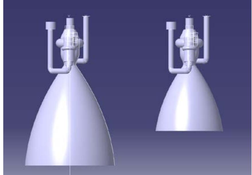
The engine masses are estimated at 3375 kg with the large nozzle for the passenger stage and at 3096 kg for the booster stage. These values are equivalent to vacuum T/W at MR=6.0 of 68.5 and 72.6. Figure 18: Size comparison of simplified CAD-shapes of SLME with e=59 (left) and ¢=33 (right)
Multiple mission launch vehicles are intentionally designed for a wide range of missions. This could reach up to interplanetary travels. This section has its focus on two typical target operations both for BFR and for the SpaceLiner: satellite transport to Earth orbit and ultrafast intercontinental passenger flight.
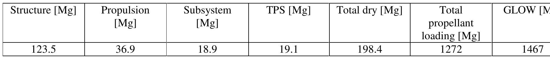
Table 12: Mass data of SpaceLiner 7-3 booster stage Table 13: Mass data of SpaceLiner 7-3 passenger stage
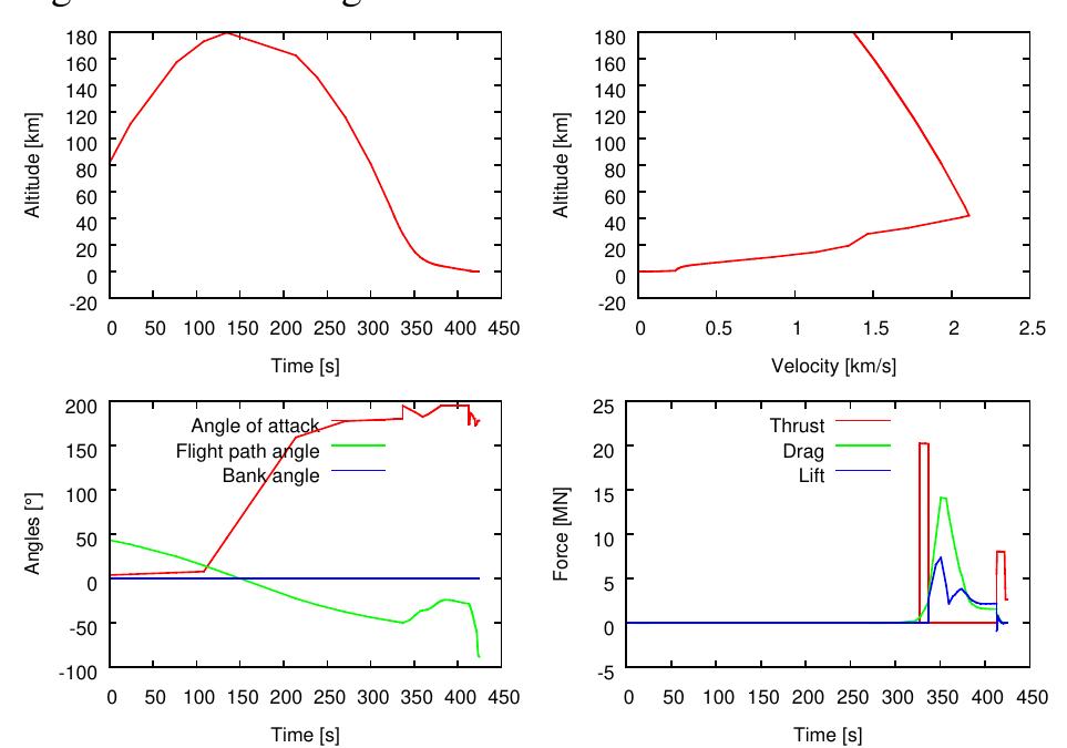
Figure 20: DLR simulation of BFR booster post- MECO flight up to final downrange landing
The corresponding trajectory optimization of a down- range landing is presented in Figure 20. A reentry burn to limit the atmospheric loads and a final landing burn is required. Despite the propulsive maneuvers, mechanical loads on the stage can reach up to 8 g and a peak dynamic pressure of close to 140 kPa. The obtained characteristics resemble those of the Falcon 9 trajec- tories. The only major difference is with the significantly larger size of the stage.
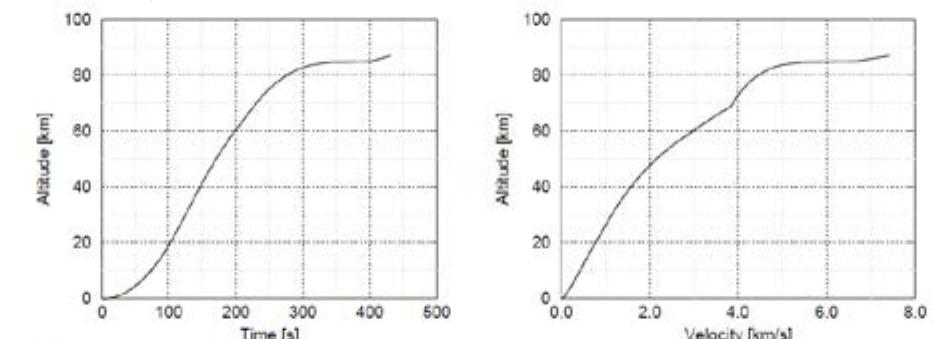
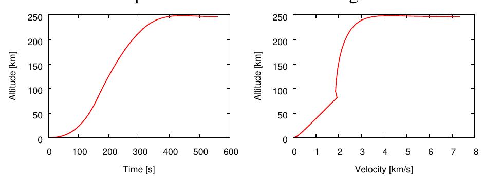
Launch of the SpaceLiner 7 TSTO has been simulated from the Kourou space center into a low 30 km x 250 km transfer orbit (Figure 21). Actually, this trajectory allows at least for the GTO mission that the orbiter stage becomes a once-around-Earth-vehicle capable of rea- ching its own launch site after a single circle around the planet. As a consequence, the achievable payload mass increases and overall complexity is reduced; e.g. an active deorbiting is not needed. Trajectory optimizations show that the orbiter is able to deliver internally more than 26150 kg of separable payload to the very low and unstable orbit. Subsequently, an orbital transfer is necessary from LEO to GTO. Figure 21: SpaceLiner ascent into 30 km x 250 km transfer orbit, GTO mission
![Figure 22: Simulated New York — Shanghai mission ascent (blue) and RTLS maneuver of BFR booster (red) Any exact position of a potential launch pad close to NYC is unknown, however, a certain safety distance has to be kept to ensure no third party harm in case of a failure or explosion on the launch pad. Hence, the launch and landing positions in NYC and Shanghai were assumed to be several kilometers from the shore. Moreover, the launch azimuth is selected such that the BFR flies over densely populated regions of the New York City metropolitan area (see Figure 22) which also seems to be supported by the video [2].](https://figures.academia-assets.com/70046141/figure_022.jpg) ](
](Figure 22: Simulated New York — Shanghai mission ascent (blue) and RTLS maneuver of BFR booster (red) Any exact position of a potential launch pad close to NYC is unknown, however, a certain safety distance has to be kept to ensure no third party harm in case of a failure or explosion on the launch pad. Hence, the launch and landing positions in NYC and Shanghai were assumed to be several kilometers from the shore. Moreover, the launch azimuth is selected such that the BFR flies over densely populated regions of the New York City metropolitan area (see Figure 22) which also seems to be supported by the video [2].
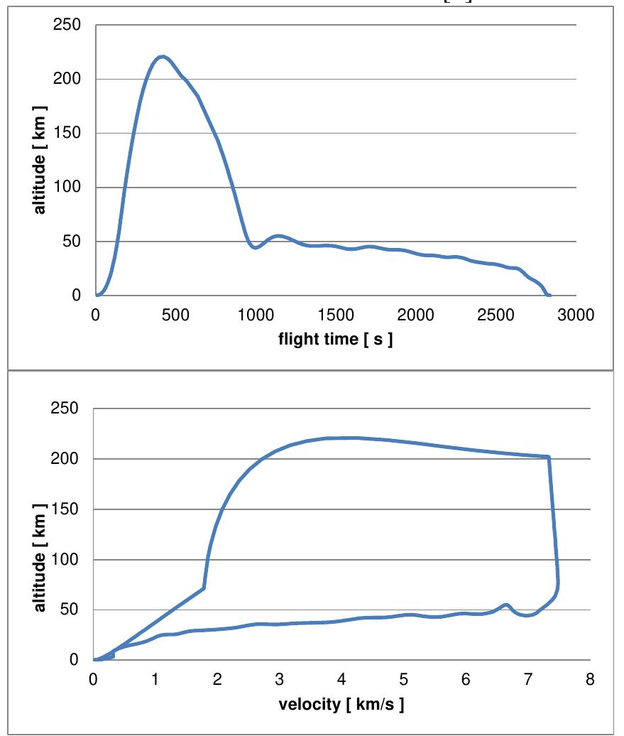
Figure 23: DLR-simulated New York — Shanghai mission profile of BFR
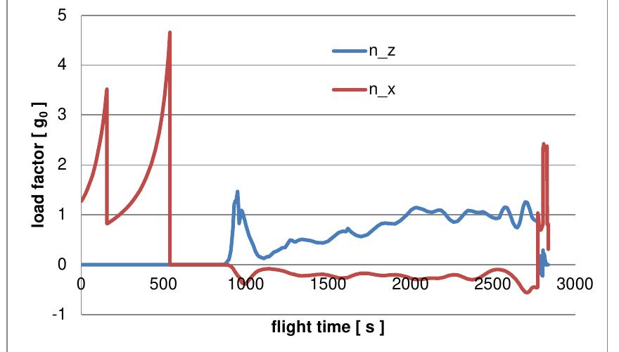
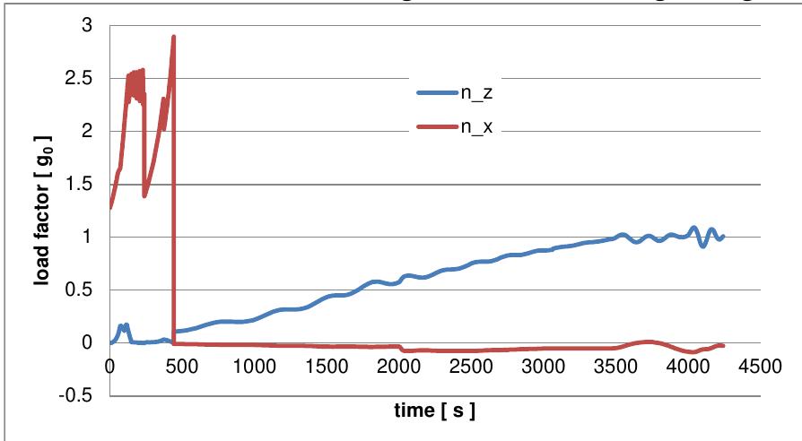
Figure 24: Load factors of DLR-simulated New York — Shanghai mission BFS The BFR has a quite steep ascent trajectory permitting reduced propellant demand for the RTLS of the booster stage and limiting noise on populated areas. As a con- sequence the reentry angles of the BFS become rela- tively large for limited performance losses. Due to the restricted lift-capability of the BFS the atmospheric de- celeration takes place in lower altitudes compared to the SpaceLiner, thus increasing the peak heatload and re- ducing the possible maximum flight range. The load factors along the flight history are depicted in Figure 24. Maximum acceleration in ascent is up to 4.5 g but might be reduced by engine throttling. After MECO the BFS is for 340 s completely weightless before the reentry loads rapidly reach about 1.5 g in lateral direction and later for powered landing slightly above 2.4 g in axial direction.
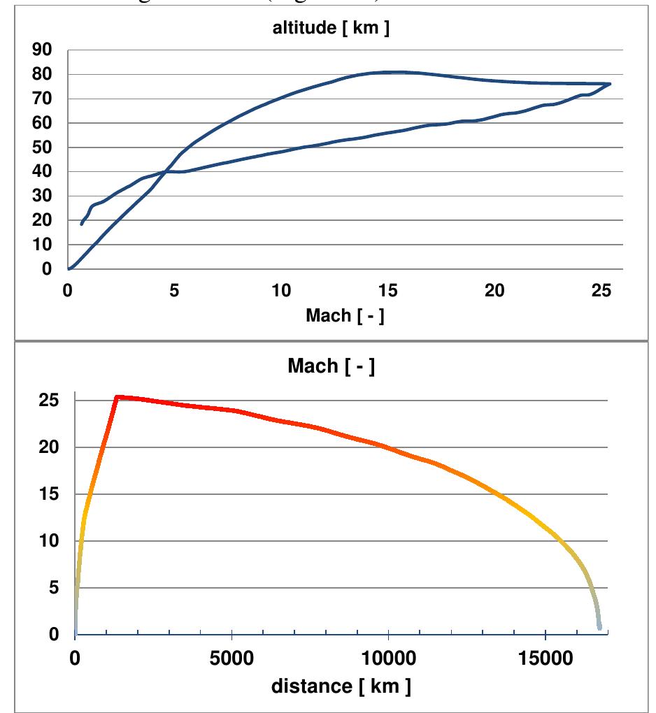
Figure 25: SpaceLiner 7-3 simulated ascent and descent trajectory data for nominal mission Australia to Europe
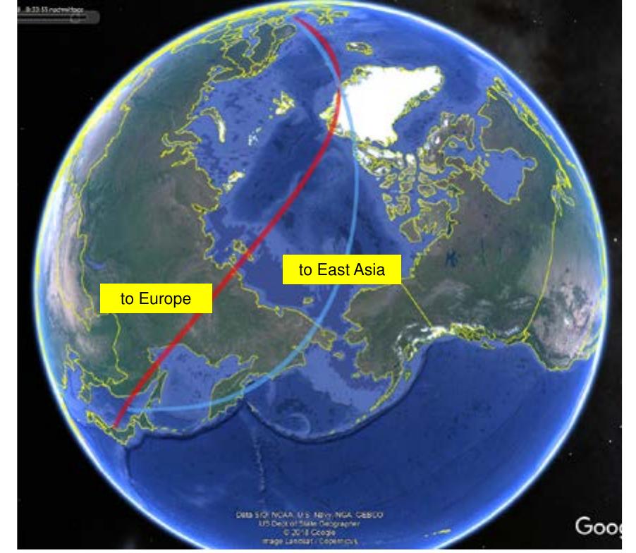
Figure 27: Potential groundtracks of SpaceLiner 7-3 nominal passenger missions Europe to East-Asia Considering the large market potential an ultrafast mission from East Asia to Europe is highly interesting. Assuming the same European launch and landing site it is not easy to find a counterpart in the far eastern region. Places in the Eastern China or Korean coastal areas had to be discarded because not finding trajectories for which ascent noise is not interfering with densely populated areas. A potentially feasible option for the site could be in the Japanese Sea from which also the Trans- Pacific route to America could be served (Figure 27).
ching the 1 g conditions in subsonic flight or on ground. The axial deceleration is benign, never exceeding -0.1 g. Figure 26: Load factors on SpaceLiner 7-3 nominal passenger mission Europe to Australia

Loading Preview
Sorry, preview is currently unavailable. You can download the paper by clicking the button above.
References (32)
- Musk, E.: Making Life Multi-Planetary, in NEW SPACE, VOL. 6, NO. 1, 2018 DOI: 10.1089/space.2018.29013.emu
- N.N.: BECOMING A MULTIPLANET SPECIES, presentation by SpaceX, 2017
- Sippel, M., Klevanski, J., Steelant, J.: Comparative Study on Options for High-Speed Intercontinental Passenger Transports: Air-Breathing-vs. Rocket- Propelled, IAC-05-D2.4.09, October 2005
- Sippel, M., Klevanski, J., van Foreest, A., Gülhan, A., Esser, B., Kuhn, M.: The SpaceLiner Concept and its Aerothermodynamic Challenges, 1 st ARA- Days, Arcachon July 2006
- Sippel, M.: Promising roadmap alternatives for the SpaceLiner, Acta Astronautica, Vol. 66, Iss. 11-12, (2010)
- Sippel, M.; Schwanekamp, T.; Trivailo, O.; Lentsch, A.: Progress of SpaceLiner Rocket- Powered High-Speed Concept, IAC-13-D2.4.05, IAC2013, Beijing, September 2013
- Van Foreest, A. , Sippel, M.; Gülhan, A.; Esser, B.; Ambrosius, B.A.C.; Sudmeijer, K.: Transpiration Cooling Using Liquid Water, Journal of Thermophysics and Heat Transfer, Vol. 23, No. 4, October-December 2009
- Sippel, M.; Klevanski, J.; Kauffmann, J.: Innovative Method for Return to the Launch Site of Reusable Winged Stages, IAF-01-V.3.08, 2001
- Sippel, M.; Klevanski, J.: Simulation of Dynamic Control Environments of the In-Air-Capturing Mechanism, 6 th International Symposium on Launcher Technology 2005, B1.4
- Sippel, M.; Bussler, L; Krause, S.; Cain, S.: Bringing Highly Efficient RLV-Return Mode "In- Air-Capturing" to Reality, HiSST 2018-1580867, 1 st HiSST: International Conference on High-Speed Vehicle Science Technology, Moscow, to be published November 2018
- Musk, E.: Making Humans a Multi-Planetary Species, in NEW SPACE, VOL. 5, NO. 2, 2017, DOI: 10.1089/space.2017.29009.emu
- Sippel, M., Wilken J.: Preliminary Component Definition of Reusable Staged-Combustion Rocket Engine, Space Propulsion 2018, Seville, May 2018
- Schwanekamp, T.; Bauer, C.; Kopp, A.: The Development of the SpaceLiner Concept and its Latest Progress, 4 TH CSA-IAA CONFERENCE ON ADVANCED SPACE TECHNOLOGY, Shanghai, September 2011
- Yamashiro, R.; Sippel, M.: Preliminary Design Study of Staged Combustion Cycle Rocket Engine for SpaceLiner High-Speed Passenger
- Transportation Concept, IAC-12-C4.1.11, Naples, October 2012
- Schwanekamp, T.; Bütünley, J.; Sippel, M.: Preliminary Multidisciplinary Design Studies on an Upgraded 100 Passenger SpaceLiner Derivative, AIAA2012-5808, 18 th AIAA International Space Planes and Hypersonic Systems and Technologies Conference, Tours, September 2012
- Bauer, C.; Garbers, N.; Sippel, M.: The SpaceLiner 7 -Vehicle and Rescue Capsule, ISTS, Nagoja 2013
- Stappert, S.; Sippel, M.; Bussler, L.; Wilken, J.; Krummen, S.: SpaceLiner Cabin Escape System Design and Simulation of Emergency Separation from its Winged Stage, AIAA 2018-5255, 22 nd AIAA International Space Planes and Hypersonic Systems and Technologies Conference, 17-19 September 2018, Orlando, Florida, USA
- Sippel, M.; Schwanekamp, T; Trivailo, O; Kopp, A; Bauer, C; Garbers, N.: SpaceLiner Technical Progress and Mission Definition, AIAA 2015- 3582, 20 th AIAA International Space Planes and Hypersonic Systems and Technologies Conference, Glasgow, July 2015
- Sippel, M.; Schwanekamp, T.; Ortelt, M.: Staged Combustion Cycle Rocket Engine Subsystem Definition for Future Advanced Passenger Transport, Space Propulsion 2014, Cologne, Germany, May 2014
- Schwanekamp, T.; Ludwig, C.; Sippel, M.: Cryogenic Propellant Tank and Feedline Design Studies in the Framework of the CHATT Project, 19 th AIAA International Space Planes and Hypersonic Systems and Technologies Conference, AIAA Aviation and Aeronautics Forum and Exposition, June 2014
- Sippel, M.; Schwanekamp, T.: The SpaceLiner Hypersonic System - Aerothermodynamic Requirements and Design Process, 8 th European Symposium on Aerothermodynamics for Space Vehicles, Lisbon, March 2015
- Bonetti, D. et al: Hypersonic Morphing for a Cabin Escape System: Results of First Design Loop, 8 th European Symposium on Aerothermodynamics for Space Vehicles, Lisbon 2015
- Schwanekamp, T.; Mayer, F.; Reimer, T.; Petkov, I.; Tröltzsch, A.; Siggel, M.: System Studies on Active Thermal Protection of a Hypersonic Suborbital Passenger Transport Vehicle, AIAA Aviation Conference, AIAA 2014-2372, Atlanta, June 2014
- Bauer, C.; Kopp, A.; Schwanekamp, T.; Clark, V.; Garbers, N.: Passenger Capsule for the SpaceLiner, DLRK-paper, Augsburg 2014
- Sippel, M.; Stappert, S.; Bussler, L.: "Systematic Assessment of a Reusable First-stage Return Options", IAC-17-D2.4.4, 68 th International Astronautical Congress, Adelaide, Australia, 25-29 September 2017, http://elib.dlr.de/114960/
- Sippel, M., Trivailo, O., Bussler, L., Lipp, S., Kaltenhäuser, S.; Molina, R.: Evolution of the SpaceLiner towards a Reusable TSTO-Launcher, IAC-16-D2.4.03, September 2016
- Sippel, M.; Bussler, L.; Kopp, A.; Krummen, S.; Valluchi, C.; Wilken, J.; Prévereaud, Y.; Vérant, J.- L.; Laroche, E.; Sourgen, E.; Bonetti, D.: Advanced Simulations of Reusable Hypersonic Rocket- Powered Stages, AIAA 2017-2170, 21 st AIAA International Space Planes and Hypersonic Systems and Technologies Conference, 6-9 March 2017, Xiamen, China
- Ponomarenko, A.: RPA -Tool for Rocket Propulsion Analysis, Space Propulsion 2014, Cologne, Germany, May 2014
- Trivailo, O.: Innovative Cost Engineering Analyses and Methods Applied to SpaceLiner -an Advanced, Hypersonic, Suborbital Spaceplane Case-Study, PhD Thesis 2015
- Trivailo, O. et.al.: SpaceLiner Mission Requirements Document, SL-MR-SART-00001- 1/2, Issue 1, Revision 2, SART TN-005/2016, 11.07.2016
- Further updated information concerning the SART space transportation concepts is available at: http://www.dlr.de/SART
FAQs
![]()
AI
What are the payload capabilities of BFR and SpaceLiner to LEO?add
The BFR, in a fully reusable configuration, potentially delivers 150 tons to LEO, while the SpaceLiner 7 can achieve over 8.2 tons with additional assistance from an expendable stage.
How does the propulsion system of BFR differ from SpaceLiner?add
BFR utilizes a Full-Flow Staged Combustion Cycle Raptor engine with LOX-LCH4, whereas SpaceLiner adopts a similar cycle but with LOX-LH2, enhancing its operational flexibility.
What implications do BFR's and SpaceLiner's designs have for intercontinental travel?add
BFR aims for ultra-fast travel between cities, promising as little as 39 minutes from New York to Shanghai, while SpaceLiner models suggest enhanced passenger comfort for long-haul flights.
What are the estimated production costs for launching SpaceLiner missions?add
Operational costs for the SpaceLiner are projected below 10 M€ for ISS resupply with specific launch costs reaching under 1000 €/kg, showcasing significant cost-saving potential.
How do the designs of BFR and SpaceLiner compare in terms of mission flexibility?add
Both concepts are designed for multiple missions; BFR emphasizes heavy payloads and interplanetary capabilities while SpaceLiner focuses on passenger transport and satellite launching.