UWB Tracking of Mobile Robots (original) (raw)
Abstract
![]()
AI
Portable ultra-wideband (UWB) radio ranging technology is employed for developing a local positioning system (LPS) aimed at tracking mobile robots. The paper focuses on addressing the challenges posed by sporadic errors in range data through the implementation of fuzzy neighborhood filters to remove outliers, and progressive trilateration filters to enhance update rates. Combining UWB data with inertial measurements, a comprehensive sensor fusion approach is presented, validated through experimental results and comparisons with video evidence.
FAQs
![]()
AI
How effective is the fuzzy neighborhood filter in removing outlier range measurements?add
The study demonstrates that the fuzzy neighborhood filter successfully eliminated large sporadic errors in range data, particularly improving accuracy in the 20 to 100 ft range.
What improvements does the progressive tracking filter provide to update rates?add
The research indicates that the progressive tracking filter offers a fourfold increase in update rates, significantly enhancing tracking performance for moving targets.
What role does sensor fusion play in the UWB tracking system?add
The implementation of sensor fusion with the Extended Kalman Filter combines trilateration measurements with wheel encoders and a compass, refining positional accuracy during movement.
What experimental validation was performed to verify tracking accuracy?add
The estimated vehicle positions were corroborated with synchronized video evidence, providing visual confirmation against the tracking outputs from the UWB system.
How does the UWB system handle multipath and attenuation challenges?add
The study reveals that while UWB radios achieve precise measurements, they face challenges from multipath and attenuation, necessitating advanced filtering techniques to maintain accuracy.
Figures (14)
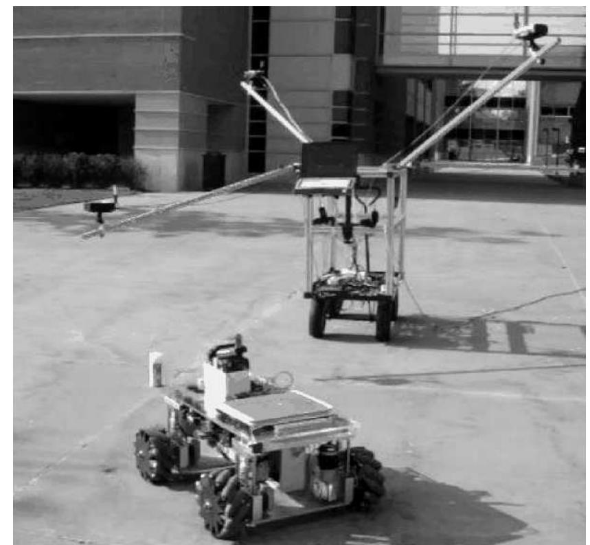
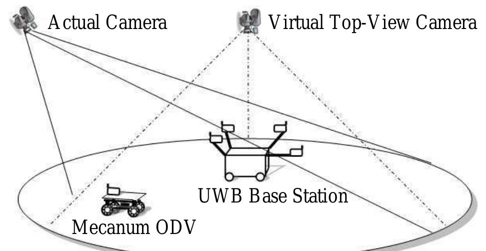
Fig. 1: UWB base station test cart and Mecanum ODV
Using four UWB ranging radios, it is possible to trilaterate the position of a fifth radio uniquely. In this paper, the fifth radio is defined as the ‘target’ radio, and the four others are the ‘base station.’ The distance between the target radio and each base station radio is measured, and used to compute the position of the target. The position of the target radio is measure according to A. Automatic Base Station Calibration To trilaterate the position of the target radio, (4) requires the coordinates of the four base station radios. In order to easily and accurately set up the base station and obtain these coordinates, a system is presented to automatically detect the configuration of the radios. This system is based on an algorithm that derives the coordinates of the base station radios
![using only measurements of the distances between each radio [4]. The coordinates of first base station radio are defined at the origin, the line between the first and second radios is defined as the x axis (y = 0), and the plane containing the first three radios is defined as the x — y plane (z = 0). Based on these assumptions: where /;; is the measured distance between radios 7 and j, and Ln, Yn ANd z, are the coordinates of base station radio n.](https://figures.academia-assets.com/2669158/figure_003.jpg) ](
](using only measurements of the distances between each radio [4]. The coordinates of first base station radio are defined at the origin, the line between the first and second radios is defined as the x axis (y = 0), and the plane containing the first three radios is defined as the x — y plane (z = 0). Based on these assumptions: where /;; is the measured distance between radios 7 and j, and Ln, Yn ANd z, are the coordinates of base station radio n.
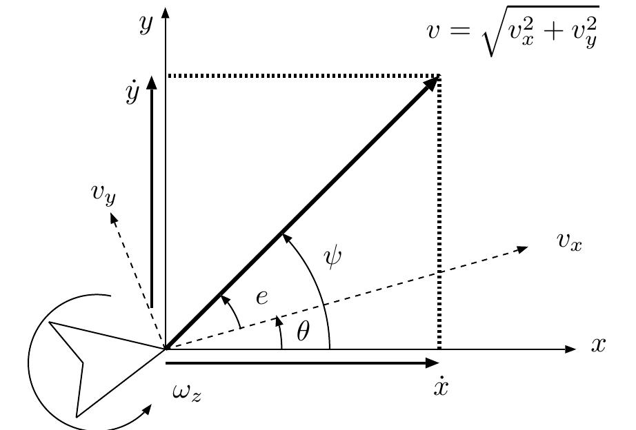
Fig. 5: Diagram outlining the kinematics of the mobile robot in UWB reference frame Fig. 5 shows a diagram from which the mode equations are derived. The x and y axes represent the reference frame defined by the UWB base station configuration. T he heading of the robot is represented by 6, the omnidirectional direction of travel is given by ¢ = tan~'(v,/v,), and the d travel in the UWB frame is given by yy = 0+¢.T irection of he velocity of the vehicle is given by vz, v, and wz, and are tl ne Same as n (11). The vehicle’s velocity in the UWB reference frame are given by «, y and 6.
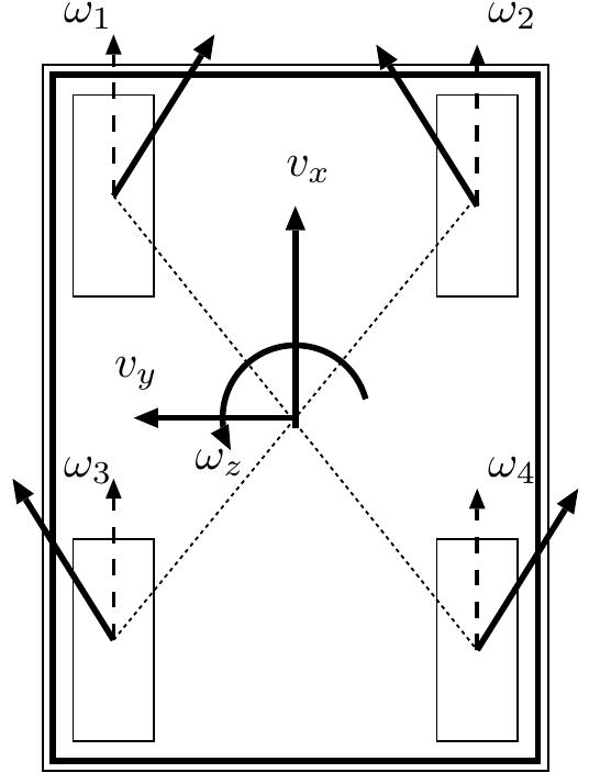
Fig. 4: Illustration of the Mecanum ODV platform
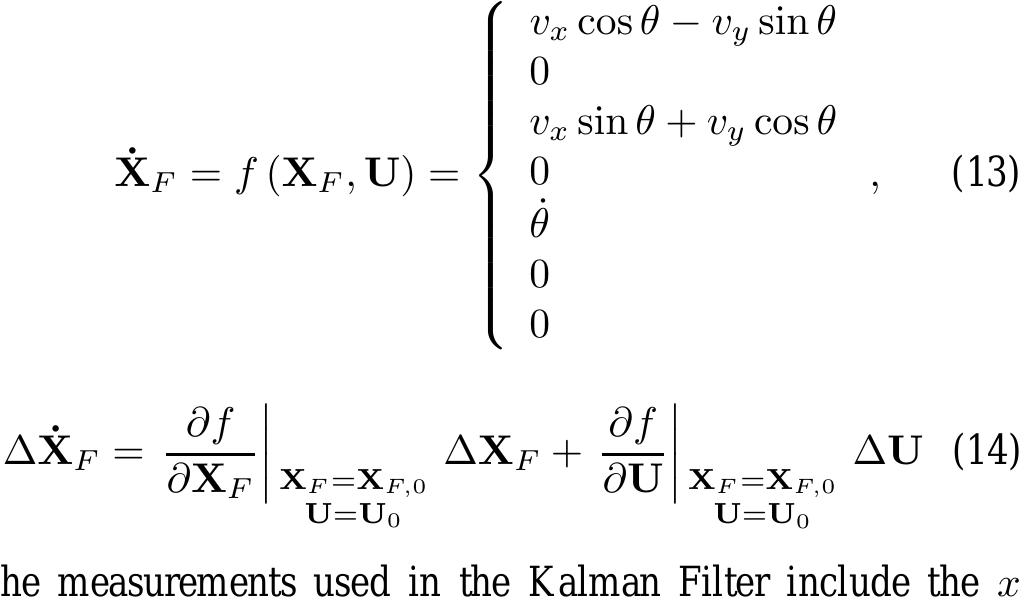
Using these definitions, the state equations are defined in (13). This non-linear system can then be linearized using a Taylor Series approximation, as shown in (14).
The recursive Extended Kalman Filter algorithm then follows the following procedure, where @ is the modelled random process noise covariance matrix and R is the measurement noise covariance matrix: The measurements used in the Kalman Filter include the x and y position estimate from the trilateration filter, the rotation speed of the vehicle as measured from the wheel encoders, and the heading of the vehicle as measured by the digital compass. As such, the measurement equation and observation matrix of the EKF are given by (15) and (16), respectively.
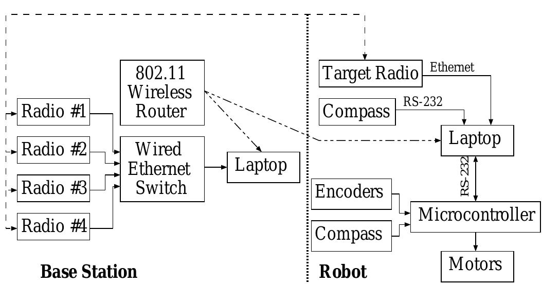
Fig. 6: Hardware architecture used in UWB tracking experi- ments The UWB tracking system described in the previous sections was implemented using the base station cart and Mecanum ODV as described in Section II. A diagram of the hardware architecture used in the experiments is shown in Fig. 6. The software diagram is shown in Fig. 7.
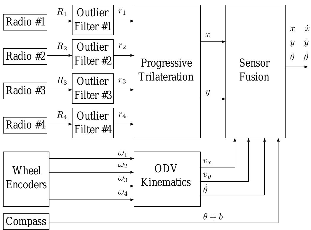
Fig. 7: Software diagram for UWB tracking with sensor fusion
frames were transformed to make it appear that the video was taken directly from overhead, so that the ground truth data from the images is simpler to extract and easier to visualize. This transformation is illustrated geometrically in Fig. 10. The transformation stages were calibrated using some simple distance measurements. Each pixel in the original image is processed through the transformation and remapped into the top-view image. A sample of the transformation procedure is shown in Fig. 11. Fig. 10: Diagram illustrating the image transformation proce- dure
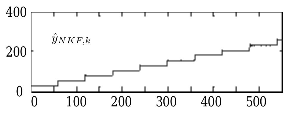
Fig. 9: Experimental data and effectiveness of FNT filters Fig. 8: Raw ranges with large sporadic multipath errors
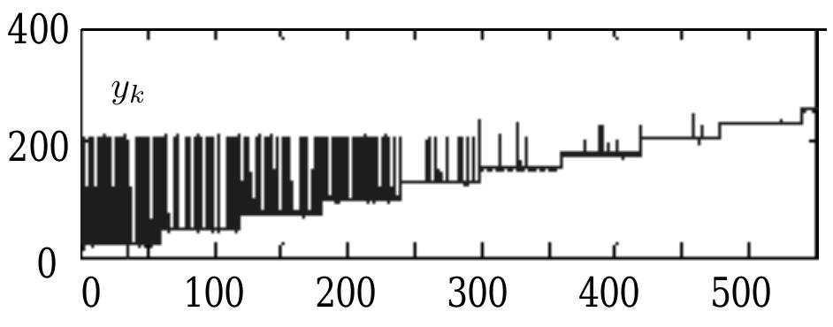
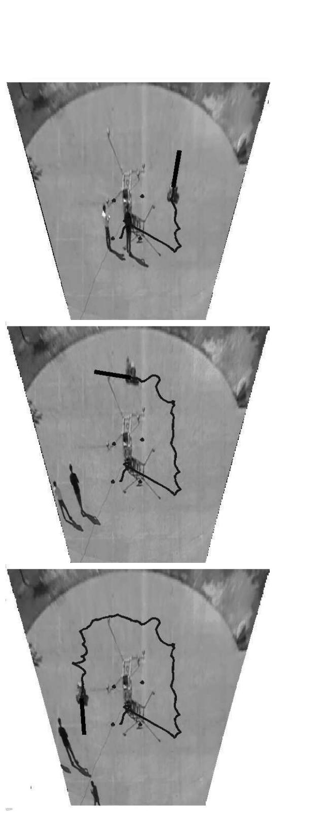
Fig. 11: Actual image and transformed top-view image

Loading Preview
Sorry, preview is currently unavailable. You can download the paper by clicking the button above.
References (13)
- R. J. Fontana, "Recent systems applications of short-pulse ultra- wideband technology," IEEE Microwave Theory & Technology, vol. 52, no. 9, September 2004.
- R. J. Fontana, E. Richley, and J. Barney, "Commercialization of an ultra wideband precision asset location system," in Proc. of the 2003 IEEE Conference on Ultra Wideband Systems and Technologies, Reston, VA, 2003.
- V. S. Sonwalkar, A. Venkatasubramanian, B. A. Johnson, and J. G. Hawkins, "UWB propagation over the ground," Electrical & Computer Eng. Dept., University of Alaska Fairbanks, Fairbanks AK-99775, USA.
- K. C. Cheok, "Navigation system," US Patent No: US 7,403,783 B2, February 2004.
- K. C. Cheok, B. Liu, G. R. Hudas, J. L. Overholt, and M. Skalny, "Ultra- wideband methods for UGV positioning: Experimental and simulation results," in Procs. of 2006 US Army Science Conference, 2006.
- G. R. Hudas, J. Overholt, K. C. Cheok, and G. Smid, "TOA & TDOA method for UWB RF location technique," in Procs. of 2004 US Army Science Conference, Orlando, FL, 2004.
- K. C. Cheok, "Ultra-wideband (UWB) local positioning system (LPS) an experimental study and analysis," in Procs of 2008 WAC ISSCI (Soft Computing), Waikoloa, HA, September 2008.
- K. C. Cheok, G. R. Hudas, and J. L. Overholt, "Fuzzy neighborhood tracking filters for uwb range radios in multipath environments," in Proc. of the 2008 SPIE Defense & Security Conference, Orlando, FL, March 2008.
- A. Gelb, Ed., Applied Optimal Estimation, 16th ed. Cambridge, Massachusetts: MIT Press, 2001, pp. 182-192.
- G. R. Hudas, "Statistical test point estimation techniques for nonlinear systems," Ph.D. dissertation, Oakland University, Dept. of Electrical and Systems Engineering, 2003.
- G. R. Hudas, K. C. Cheok, and J. L. Overholt, NAFIPS'05 Special Issue of the Int. J. of Approximate Reasoning. Elsevier, 2006, ch. Fuzzy Variant of a Statistical Test Point Kalman Filter.
- J. L. Overholt, K. C. Cheok, and G. E. Smid, "Threshold fuzzy systems: A priority based hierarchical control scheme," in Proc. of the 1999 American Control Conference (ACC), San Diego, USA, 1999.
- --, "Control of multi-objective plants using threshold fuzzy systems: Basic concepts," in World Automation Congress (WAC), Alaska, 1998.