Investigation of thermal conductivity of PCB (original) (raw)
Abstract
The thermal conductivity of PCB structures variations according to the position of the metal layers as a function of the local copper contents and distribution are studied. The value of the parallel and serial thermal conductivity coefficient of PCB have been calculated by usage of the corresponding electrical analogs of parallel and serial resistive systems. Solutions were obtained for two PCB thicknesses. Cases with and without a copper layer on the component side were investigated. Simulated results are verified with infrared thermovision measurements.
FAQs
![]()
AI
What role do component sizes play in PCB thermal conductivity?add
The investigation reveals that effective thermal conductivities of PCBs increase with larger component sizes, demonstrating a significant dependency that deviates from one-dimensional assumptions.
How does the thermal resistance between layers affect PCB performance?add
The study finds that neglecting thermal contact resistance between copper and glass-epoxy layers can lead to substantial inaccuracies in predicted thermal performance.
What are the effective thermal conductivities determined for the PCB under study?add
For the described PCB setup, the effective parallel thermal conductivity was noted as 25.83 W/m°C, while the normal thermal conductivity was significantly lower at 0.268 W/m°C.
What methodology was employed to simulate PCB thermal behavior?add
Numerical solutions of the three-dimensional heat conduction equation using ANSYS CFD software provided detailed evaluations of the PCB's thermal performance under varying conditions.
How does PCB modeling impact thermal management in microelectronic devices?add
The results indicate that traditional 1D models may underestimate thermal effects, emphasizing the need for more accurate three-dimensional models to predict heat transfer effectively.
Figures (8)
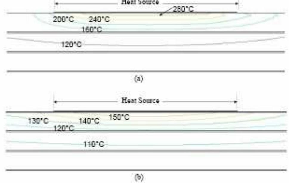
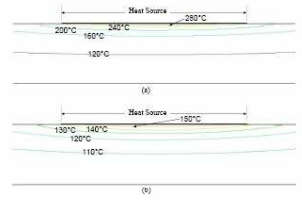
Fig.2 Temperature contours in a 1.6 mm thick PCB with two internal copper layers; (a) no copper layer on top surface (b) copper layer on top surface.
![PCBs are usually modeled as single objects with parallel (in the plane of the board) and normal (perpendicular to the board) effective thermal conductivities. The effective parallel and normal thermal conductivities, kj_~ and ky, are typically calculated assuming one-dimensional heat conduction through a composite layer [4], and neglecting the thermal contact resistance between the copper and glass-epoxy layers [5]. For a PCB with N, number of copper layers and Ng number of glass-epoxy layers](https://figures.academia-assets.com/49079515/figure_003.jpg) ](
](PCBs are usually modeled as single objects with parallel (in the plane of the board) and normal (perpendicular to the board) effective thermal conductivities. The effective parallel and normal thermal conductivities, kj_~ and ky, are typically calculated assuming one-dimensional heat conduction through a composite layer [4], and neglecting the thermal contact resistance between the copper and glass-epoxy layers [5]. For a PCB with N, number of copper layers and Ng number of glass-epoxy layers
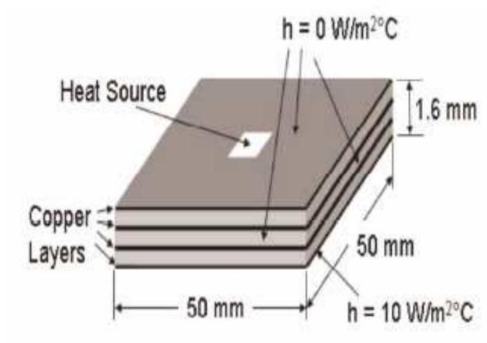
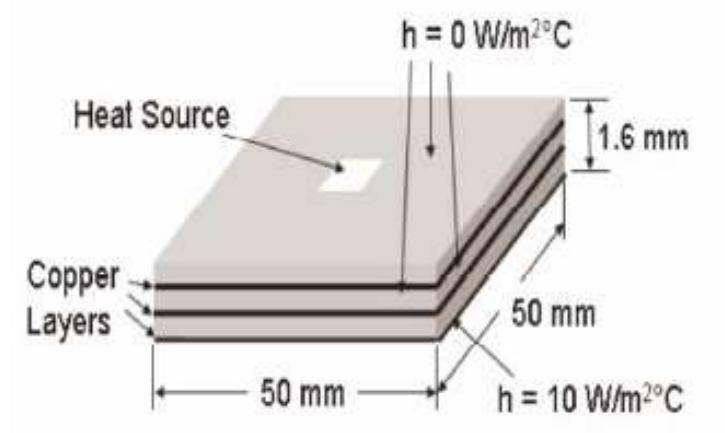
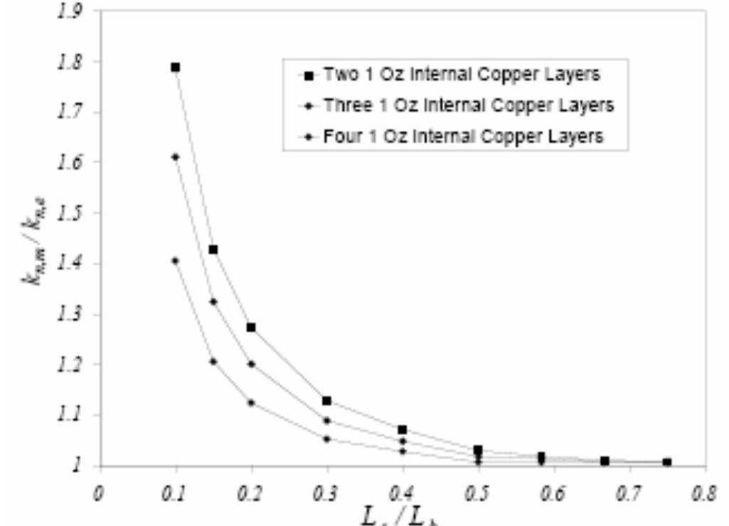
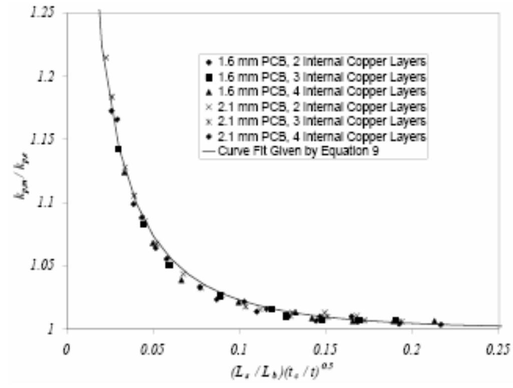
For given boundary conditions, the maximum heat source temperature, T,, and the maximum temperature of the board opposite the heat source, T;, are functions of the PCB length, Lp, and thickness, t, number of copper layers, N,, thickness of the ith copper layer, t,,;, number of glassepoxy layers, Ng, thickness of the ith glass-epoxy layer, t,i, thermal conductivities of copper and glass-epoxy, k, and ky, and the length of the heat source ,Ls.
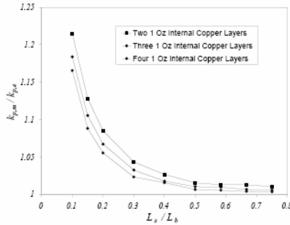
numerical solution of the heat conduction equation in the orthotropic model of the same PCB (the second model mentioned above) was obtained with a given set o1 parallel and normal thermal conductivities. These thermal conductivities were iteratively corrected such that the maximum heat source temperature and_ the maximum PCB temperature opposite the heat source were predicted within 1% of the values predicted by the detailed PCB simulation. The PCB model that uses these thermal conductivities was called the “modified effective thermal conductivity’ model (MM). Two convergence criteria were used for all the numerical solutions reduction of the residual of the temperature equation below 10°” and less that 0.1% variation in the maximum source temperature in each iteration. Fig. 4 shows the temperature distribution across the PCB model for the MM model. The MM mode. nrovides hetter nredictiogns of _ the

Loading Preview
Sorry, preview is currently unavailable. You can download the paper by clicking the button above.
References (7)
- REFERENCES
- Błąd G., D. Klepacki, J. Potencki, A. Andonova, Application of Electro-Thermal Analogyfor Complex Simulationof Hybrid Power Controllers, Proceedinfs of ICEST, July, 2006, pp. -.
- Shaukatullah H. and M. Gaynes, Experimental Determination of the Effect of Printed Circuit Card Conductivity on the Thermal Performance of Surface Mount Electronic Packages, Proceedings of SEMI-THERM Symposium, February 1994, pp. 44 -52.
- Lohan J., P. Tiilikka, P. Rodgers, C-M. Fager and J. Rantala, Using Experimental Analysis to Evaluate the Influence of Printed Circuit Board Construction on the Thermal Performance of Four Package Types in both Natural and Forced Convection, Proceedings of the ITherm, Vol. 2, May, 2000, pp. 213 -225.
- Cengel Y., Heat Transfer, A Practical Approach, McGraw-Hill, 1998.
- Błąd G., D. Klepacki, J. Potencki, A. Andonova, Application of Electro-Thermal Analogyfor Complex Simulationof Hybrid Power Controllers, Proceedinfs of ICEST, July, 2006, pp.262 -265.
- ANSYS Solutions, www.ansys.com