Microfluidic for Lab-on-a-Chip (original) (raw)
Abstract
2.13.7.3 Application Examples 47 2.13.7.3.1 TopSpot for microarray spotting 47 2.13.7.3.2 Dispensing well plate 48 2.13.7.4 Strengths and Challenges of the Platform 49 2.13.8 Conclusion 49 References 49 Glossary g9000 CMOS Complementary Metal Oxide Semiconductor g9005 DWP Dispensing Well Plate g9010 EDC/NHS Carbodiimid/N-hydroxysuccinimide g9015 EOF Electroosmotic Flow g9020 EP Electrophoresis g9025 EWOD Electrowetting g9030 FID Free Interface Diffusion g9035 GC Gas Chromatograph g9040 HPLC High Pressure Liquid Chromatograph g9045 HTS High Throughput Screening g9050 IDT Interdigital Transducer g9055 LSI (microfluidic) Large Scale Integration g9060 MSL Multilayer Soft Lithography g9065 PCR Polymerase Chain Reaction g9070 PDMS Polydimethylsiloxane g9075 SAW Surface Acoustic Wave g9080 TAS Total Chemical-analysis System g9085 TIR Total Internal Reflection g9090 mTAS micro Total Analysis System s0005 2.13.1 Introduction s0010 2.13.1.1 Microfluidics
FAQs
![]()
AI
What key advancements marked the evolution of microfluidic technologies?add
The paper highlights significant milestones such as the development of the first high-pressure liquid chromatography column in 1985 and the incorporation of microvalves and micropumps by the late 1980s.
How do microfluidic platforms enhance analytical performance over traditional methods?add
The study reveals that microfluidic systems exploit increased surface-to-volume ratios, allowing for rapid thermal responses and enhanced laminar flow, improving analytical efficiency significantly.
What are the future market projections for microfluidic technologies in life sciences?add
The research forecasts a growth rate exceeding 30% annually for microfluidic products in life sciences, potentially reaching a market valuation of 1.4 billion euros by 2008.
Why is a system-oriented approach favored in developing microfluidic platforms?add
The research advocates for integrated microfluidic platforms that provide validated fluidic operations to streamline application-specific systems, reducing costs and development time compared to discrete component approaches.
What challenges exist in the current microfluidic platform development landscape?add
The paper identifies issues like lacking standardization for interconnections and fabrication technologies, which hinder the efficient integration of diverse platforms and components in microfluidics.
Figures (45)
Stefan Haeberle’’? and Roland Zengerle*”, ' Institute for Micromachining and Information Technology ot the Hahn-Schickard-Society (HSG-IMIT), Villingen-Schwenningen, Germany, *Laboratory for MEMS Applications, Department of Microsystems Engineering (IMTEK), University of Freiburg, Freiburg, Germany
Figure 2 Photo of a drug delivery system that can £O( be implanted into a human denture. (Source: Goettsche T, Wolff, A 2006 IntelliDrug — An integrated intelligent oral drug delivery system. mst-news 06, 36-7.) (mechanical loads, wide temperature range, and con- tact withany kind of food) inside the human mouth.
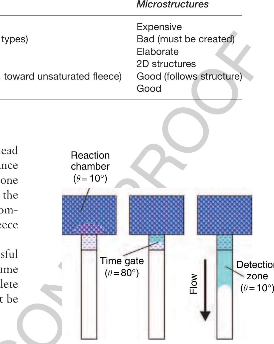
Figure 4 Schematic realization of a certain incubation £0 time in the capillary-driven test strip platform. The liquid flow is throttled in the time gate of reduced wettability (6 = 80°) thus leading to an extended period of time for reaction within the reaction chamber. Consequently, the dried reagents can be dissolved completely before the liquid proceeds along the detection zone. ble 3 Comparison of fleeces and microstructures for capillary propulsion in test strips
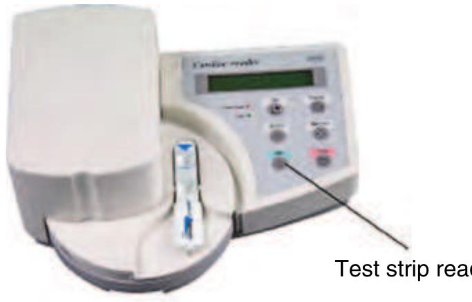
Test strips for cardiac markers
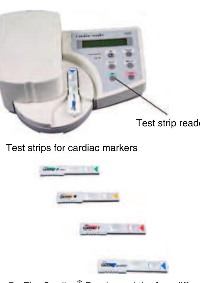
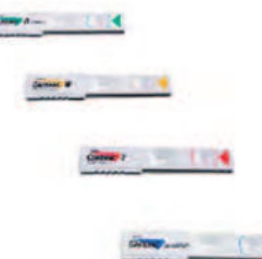
Figure 5 The Cardiac® Reader and the four different test f9925 strips (Source: Roche 2006 Basel, CH, www.roche.com, accessed 2006.)
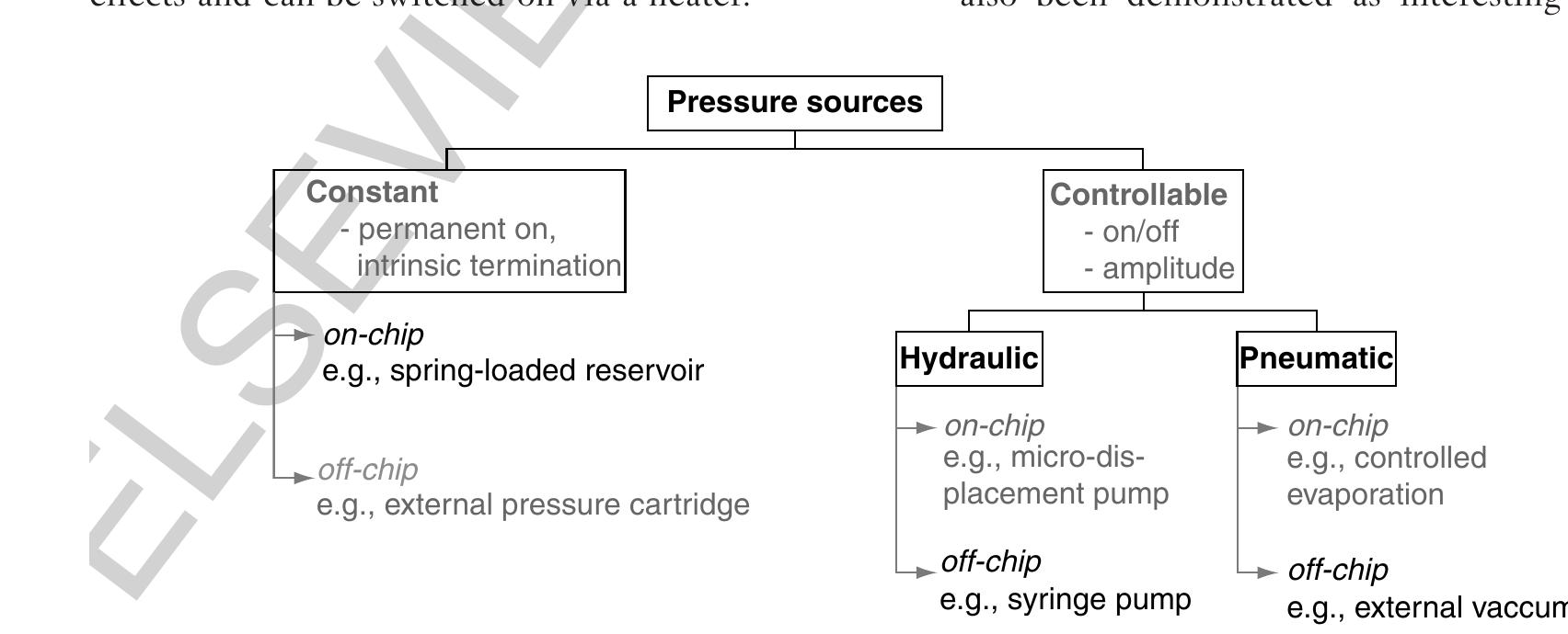
0030 Figure 6 Different pressure sources for microfluidic platforms.
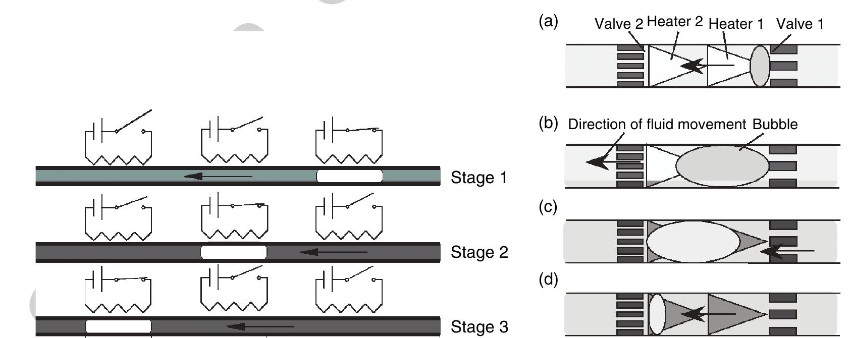
b0690 )35 Figure 7 Left: |llustration of the phase-change pumping mechanism proposed by Song and Zhao (2001). Three serial-aligned and sequentially actuated heating elements initiate a moving vapor bubble and thus a directed liquid propulsion (stages 1-3). (Source: Song Y J, Zhao T S 2001 Modelling and test of a thermally-driven phase-change nonmechanical micropump. J. Micromech. Microeng. 11, 713-19, |OP Publishing Limited.) Right: Basic principle of the thermal micropump described in (a) start of heating (heater 1 on, heater 2 off); (6) bubble growing (heaters 1 and 2 on); (c) start of condensing (heater 1 off, heater 2 on); (d) bubble collapsing (heaters 1 and 2 off). (Reprinted with permission from Yokoyama Y, Takeda M, Umemoto T, Ogushi T 2004 Thermal micro pumps for a loop-type micro channel. Sens. Actuators A Phys. 111, 123-8. Copyright 2004 Elsevier.)
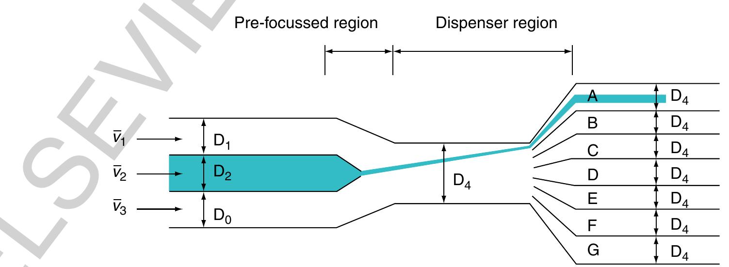
945 Figure 9 Principle of the continuous flow switch based on hydrodynamic focusing. The liquid stream V2 is focused by two lateral flows v, and v3 within the prefocused region and then deflected into one of seven outlets (A-G) within the dispenser region. (Source: Lee G B, Hung C |, Ke B J, Huang G R, Hwei B H 2001a Micromachined pre-focused 1 xN flow switches for continuous sample injection. J. Micromech. Microeng. 11, 567-73, IOP Publishing Limited.)
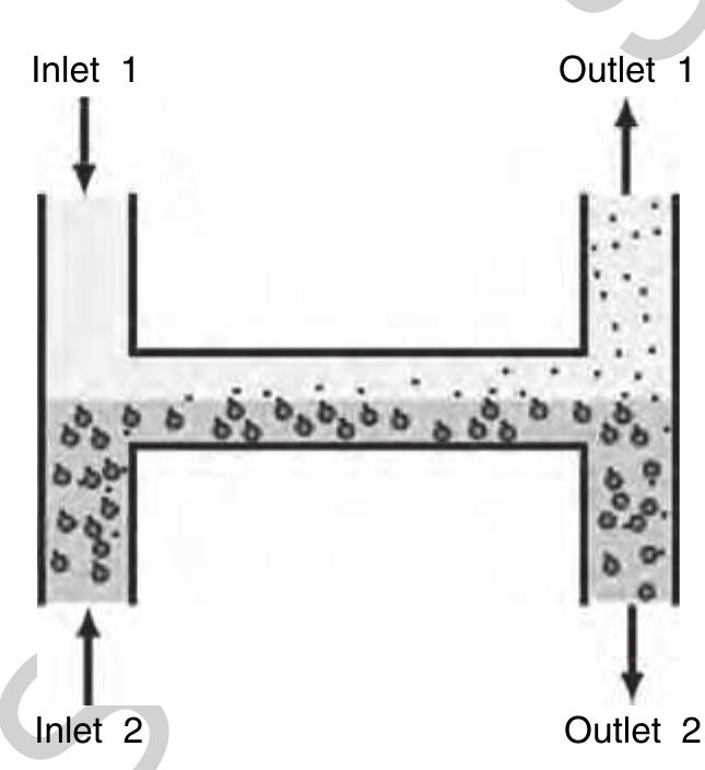
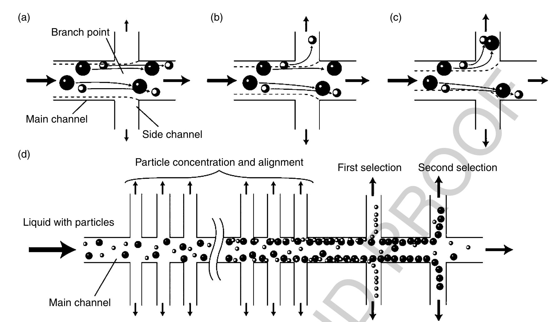
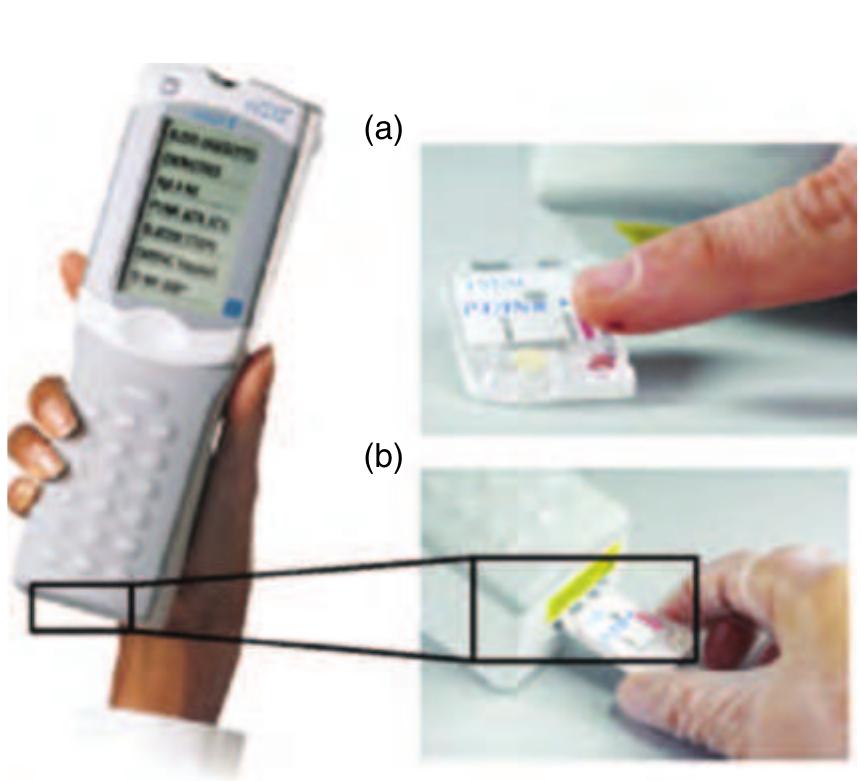
Figure 12 Left: The portable i-STAT® analyzer for clinical blood tests. Right: Depending on the blood parameters to be measured, (a) a certain disposable cartridge is filled with blood by capillary forces from the fingertip and (b) later loaded into the analyzer for assay processing and readout. (Source: Abbott P-C 2006 East Windsor, NJ, USA, www.abbottpointofcare.com, accessed 2006.)
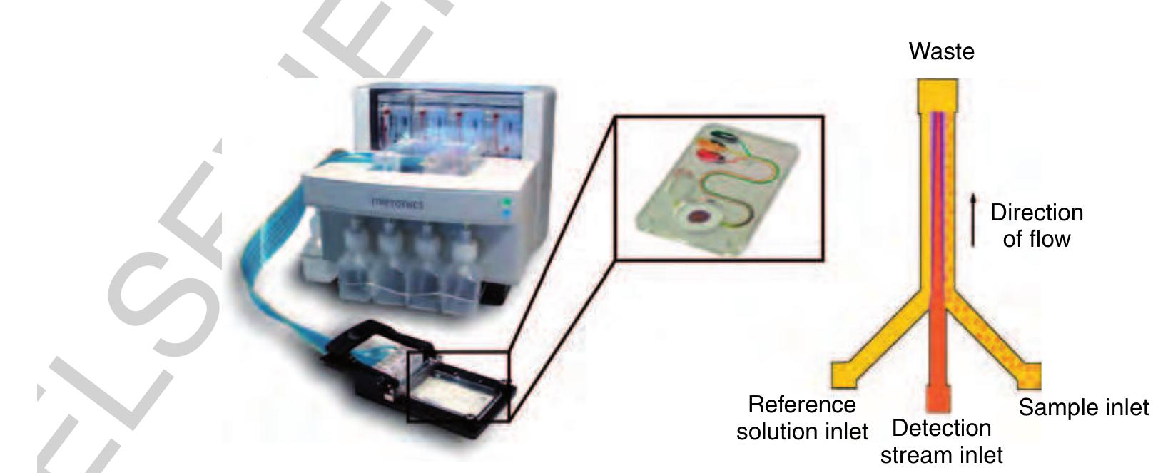
f0065 Figure 13 Left: The microFlow™ platform with an ActiveT™ card in the insert. Right: The functional principle of the T-Sensor® structure. The detection stream meets at the junction part with a reference liquid on the left and the sample liquid on the right side, respectively. (Source: Micronics Inc. 2006 Redmond, WA, USA, www.micronics.net, accessed 2006.)
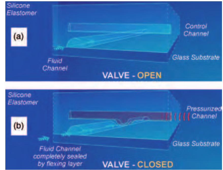
Figure 15 Schematic sketch of the microfluidic f( NanoFlex™ valve realized in the multilayer soft lithography (MSL) technology. (a) Liquid can pass through the fluid channel as long as no pressure is applied to the control channel. (6) An.increased pressure within the control channel causes the thin elastic polydimethylsiloxane (PDMS) membrane between the two channel layers to deflect into the fluid channel and blocks the liquid flow therein, i.e., the valve is closed. (Source: Fluidigm Corporation 2006 San Francisco, USA, www.fluidigm.com, accessed 2006.)
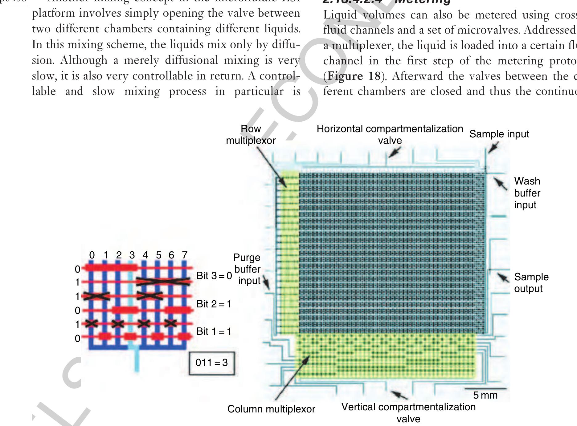
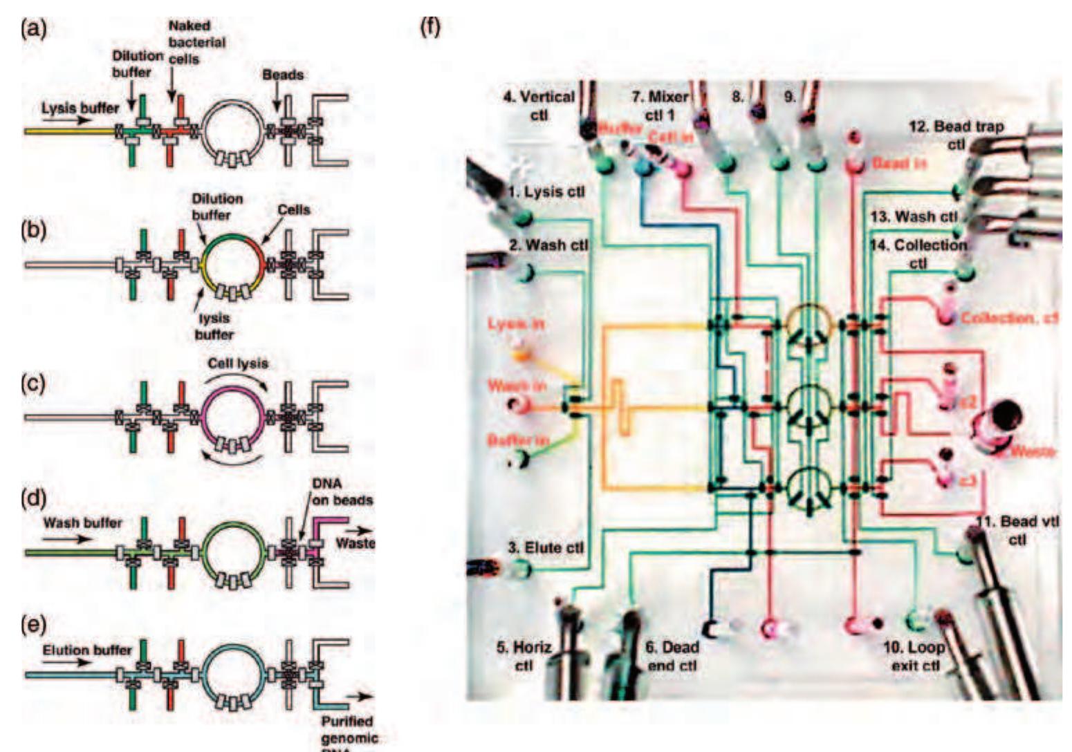
35 Figure.17 Left: Operational diagram of the microfluidic multiplexer: eight vertical fluid channels can be individually controlled by six horizontal control channels. The pressurized control channels block the fluid channels only at positions where the width of the control channel is widened. Right: Mask design for the microfluidic memory storage device. (Reprinted with permission from Thorsen T, Maerkl S J, Quake S R 2002 Microfluidic large-scale integration. Science 298, 580-4. Copyright 2002 AAAS.)
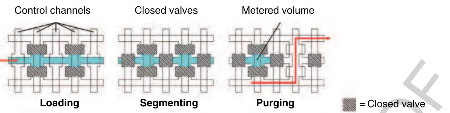
) Figure 18 Using crossed fluid channels, liquid metering is also possible on the microfluidic large-scale integration (LSI) platform. In the first loading step, a certain fluid channel is addressed using the multiplexer structure and filled with liquid. Ir the second step, the liquid within that channel is segmented by closing the valves between the chambers. In the last step, fluic that should not be kept is purged via two additional fluid channels on both sides of the metering channel.
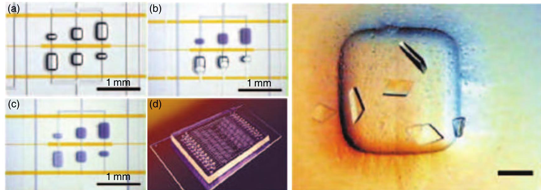
(0095 Figure 19 = Left: Microfluidic crystallization structures. (a) Three crystallization assays with different mixing ratios (1:4, 1:1, 4:1) and a fixed total volume of 25nl. (b) The central interface valve is closed and the chamber is filled with solution while the air diffuses through the bulk elastomer. (c) The intermediate valve is opened, initiating the diffusional mixing process. (d) The complete chip features 48 unit cells performing 144 simultaneous crystallization experiments while using 3 pl of protein sample only. Right: Example of protein crystals grown in the described microfluidic structure (scale bar, 100 tum). They have been grown within 12 h only, while the conventional process takes over a week. (Reprinted with permission from Hansen C, Quake S R 2003 Microfluidics in structural biology: Smaller, faster- -- better. Curr. Opin. Struct. Biol. 13, 538-44. Copyright 2003 Eksevier.)
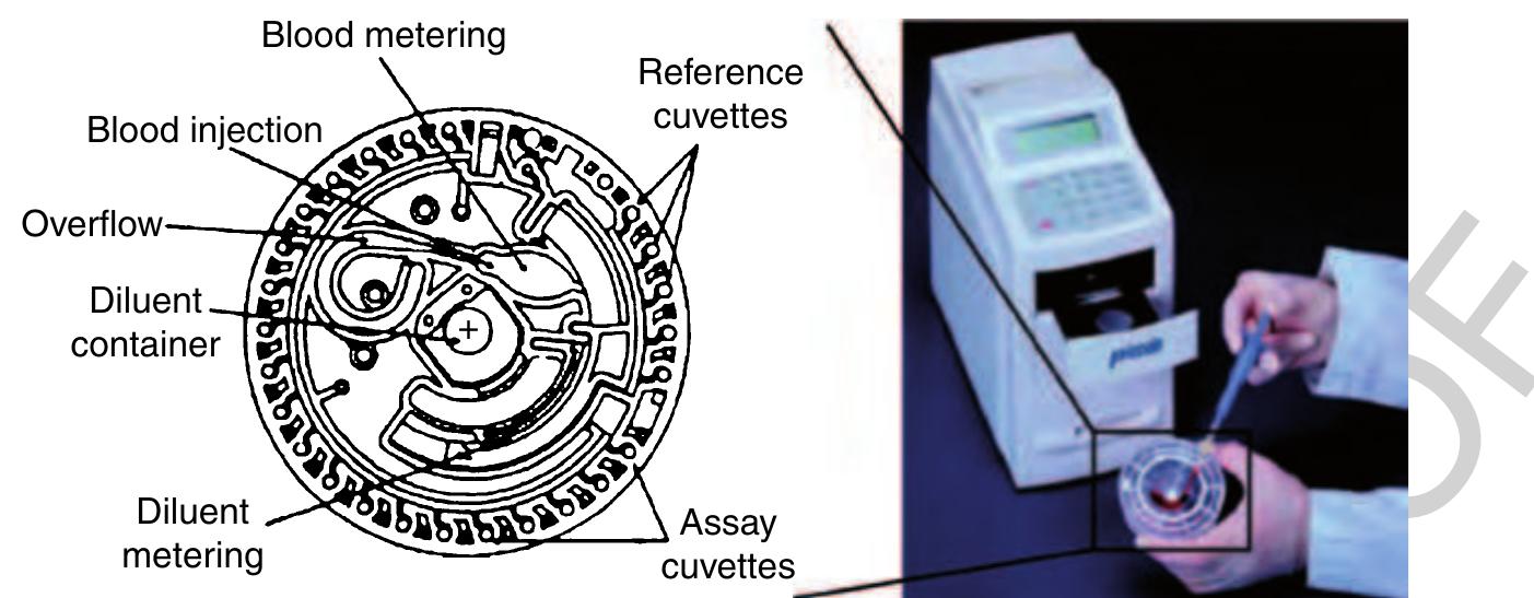
)5 Figure 21 Left: Schematic of the rotor comprising the fluidic channels, reservoirs, and the cuvettes for optical detection. (Source ~ Schembri C T, Ostoich V, Lingane P J, Burd TL, Buhl S N 1992 Portable simultaneous multiple analyte whole-blood analyzer for point-of-care testing. Clin. Chem. 38, 1665-70. Reproduced by permission of American Association for Clinical chemistry.) Right Image of the portable analyzer. (Source: Abaxis Inc. 2006 Union City, CA, USA, www.abaxis.com, accessed 2006.)
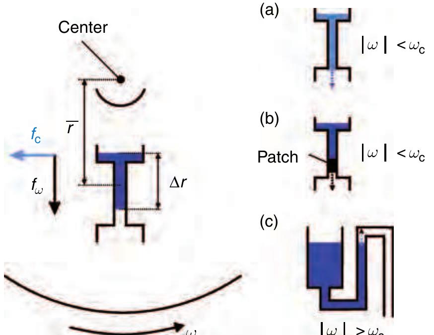
Figure 22 Principal centrifugal approach and schematic £941 sketch of the three valving techniques on the centrifugal a platform. (a) Geometric capillary valve, (b) hydrophobic valve, and (c) hydrophilic siphon valve.
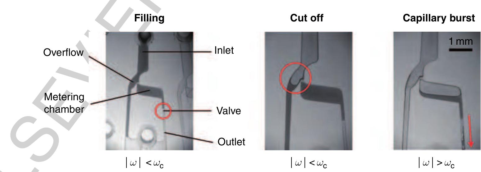
15 Figure 23 Metering structure based on a hydrophobic valve. In the initial filling stage, the fluid network is primed with an undefined sample volume. After the metering chamber is filled, the residual fluid is cut off at a frequency still beyond the critical burst frequency of the valve we. In the last step the frequency is increased over the burst frequency of the valve leading to a radial drainage of the metered volume through the structures outlet. (Source: Steigert J, Grumann M, Brenner T, Riegger L, Harter J, Zengerle R, Ducrée J 2006 Fully integrated whole blood testing by real-time absorption measurement on a centrifugal platform. Lab Chip 6, 1040-4. Reproduced by permission of The Royal Society of Chemistry.) 30260 2.13.5.2.3 Metering and aliquotting
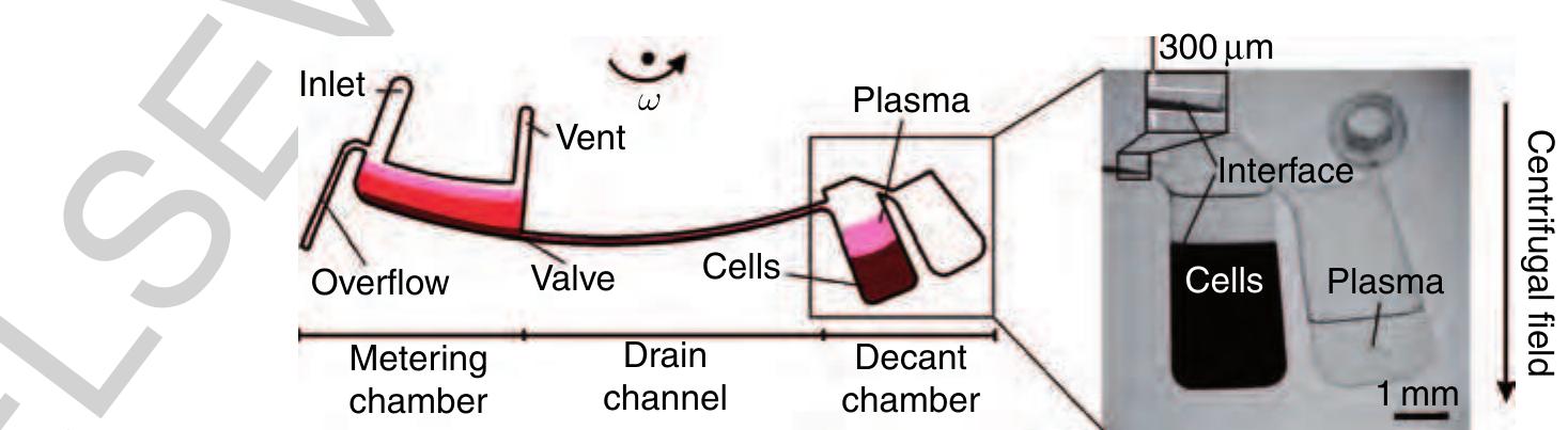
1135 Figure 27 Left: Flow scheme of the decanting structure for plasma extraction from a raw blood sample. Right: Purified ~ plasma is decanted into a separate reservoir while the cellular pellet is retained at the bottom of the decant chamber. (Source: Haeberle S, Brenner T, Zengerle R, Ducree J 2006a Centrifugal extraction of plasma from whole blood on a rotating disk. Lab Chip 6, 776-81. Reproduced by permission of The Royal Society of Chemistry.)
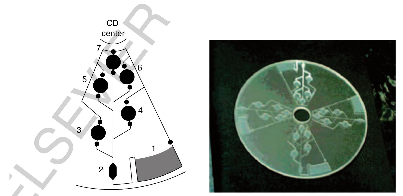
1149 Figure 28 Left: Channel design for the enzyme-linked immunosorbent assay (ELISA) assay. Several reservoirs containing different sample and washing solutions can be opened serially depending on the frequency of rotation. Right: Picture of the compact disk fabricated by computer numerical control (CNC) milling with four identical assay structures. (Reprinted with permission from Lai S, Wang S, Luo J, Lee LJ, Yang S T, Madou M J 2004 Design of a compact disk-like microfluidic platform for enzyme-linked immunosorbent assay. Anal. Chem. 76, 1832-7. Copyright 2004 American Chemical Society.)
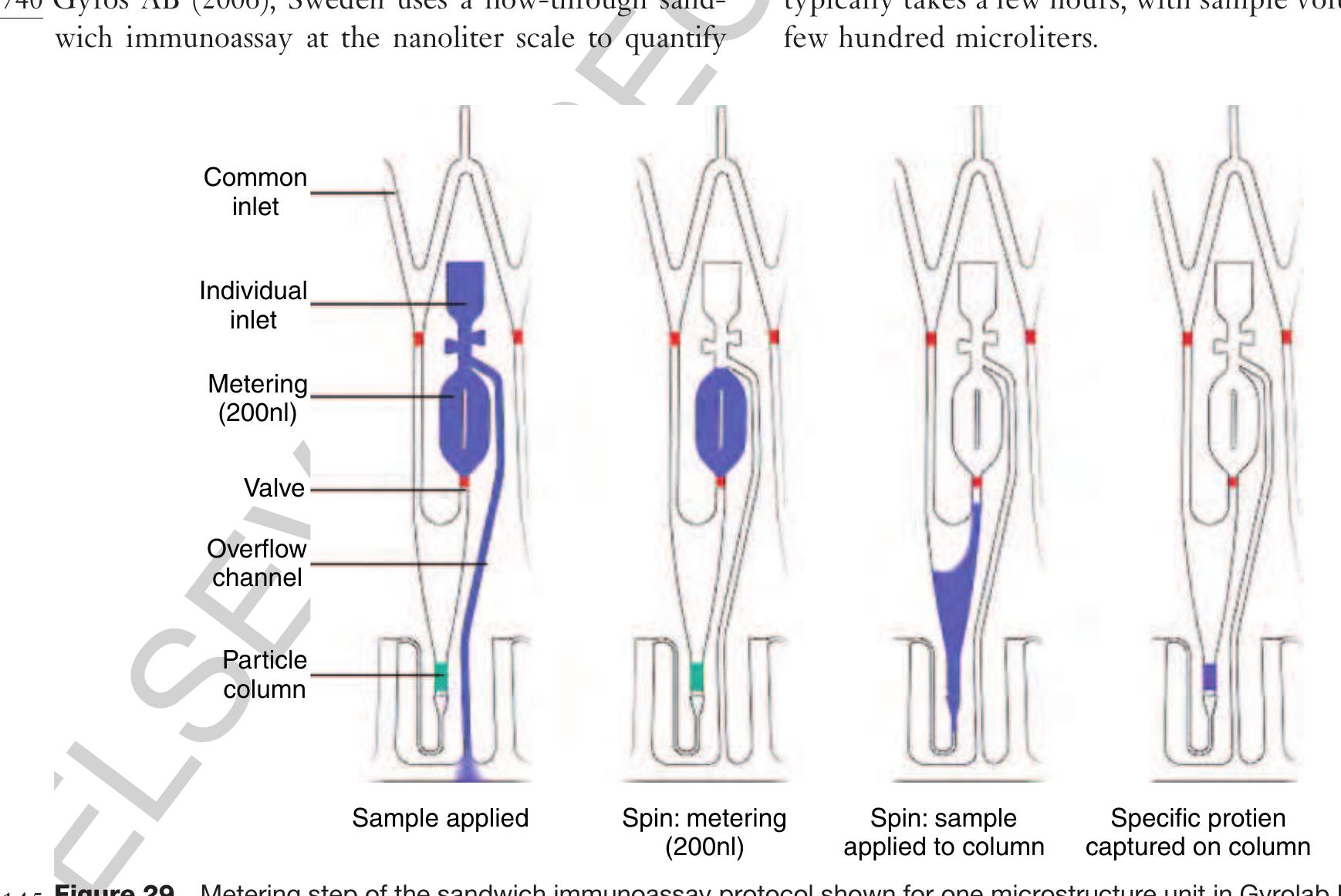
30300 2.13.5.3.3 Protein quantification (Gyrolab Bioaffy®) bO275
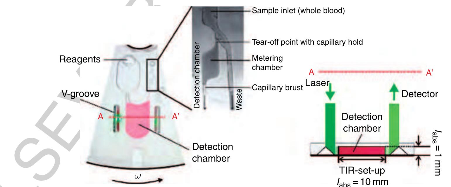
150 Figure 30 Left: Microfluidic structure for the fully integrated alcohol determination starting from a raw sample of human blood. First, the sample is metered and then mixed with the reagent within the detection chamber. Right: Readout is accomplished by the total inner reflection of a laser beam into the disk plane to elongate the optical path length /aps from approximately 1 to 10 mm (TIR set-up). (Source: Steigert J, Grumann M, Brenner T, Riegger L, Harter J, Zengerle R, Ducrée J 2006 Fully integrated whole blood testing by real-time absorption measurement on a centrifugal platform. Lab Chip 6, 1040-4. Reproduced by permission of The Royal Society of Chemistry.)
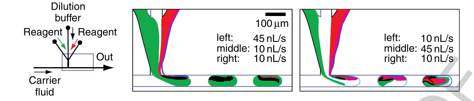
1160 Figure 32 On-chip dilution depicted with two exemplary situations at the droplet formation T-junction. Different flow rates of the reagent streams (food dye colored green and red), separated by the transparent dilution buffer stream in the middle, are injected into the droplet. Different concentrations of the two reagents are then loaded into the droplet for reaction. (Reprinted with permission from Song H, Ismagilov R F 2003 Millisecond kinetics on a microfluidic chip using nanoliters of reagents. J. Am. Chem. Soc. 125, 14613-19. Copyright 2003 American Chemical Society.) stable since no liquid is exchanged between the plug interspaces. This way, plugs can be moved spatially separated through a channel network.
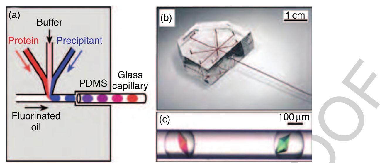
79 Figure 34 (a) Schematic illustration of the protein crystallization device and (b) the complete set-up consisting of a polydimethylsiloxane (PDMS) chip and a glass capillary. (c) Examples of thaumatin crystals that were grown inside droplets in a capillary. (Source: Zheng B, Tice J D, Roach L S, Ismagilov R F 2004c A droplet-based, composite PDMS/glass capillary microfluidic system for evaluating protein crystallization conditions by microbatch and vapor-diffusion methods with on-chip X-ray diffraction. Angew. Chem. Int. Ed. 43, 2508-11. Reproduced by permission of Wiley VCH.)
gq Figure 36 Droplet formation from an on-chip reservoir using electrowetting forces only. First, a liquid column is extruded from the reservoir and tears off after the connecting electrode is turned off. (Source: Srinivasan V, Pamula V K, Fair R B 200: An integrated digital microfluidic lab-on-a-chip for clinical diagnostics on human physiological fluids. Lab Chip 4, 310-15. Reproduced by permission of The Royal society of Chemistry.)
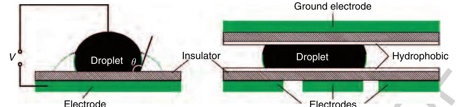
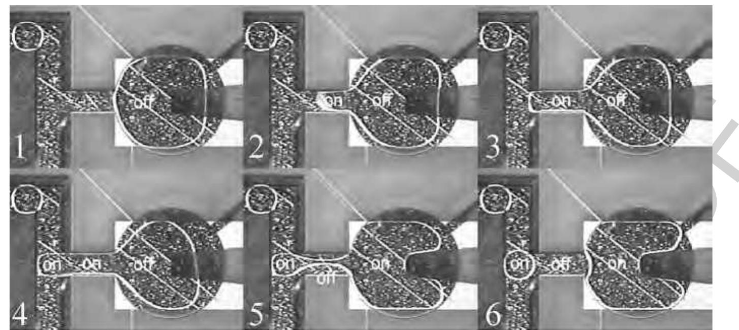
185 Figure37 Asequence of photographs showing the droplet splitting and merging. (a) Initially, only the left electrode is activated. (b) The middle electrode is then activated and, (c) and (d) after a delay, the voltage is switched from the middle to the right electrode resulting in division of the droplet. (e) and (f) The original droplet is reassembled by switching the voltage on the right electrode back to the middle electrode. (Source: Pollack M G, Shenderov A D, Fair R B 2002 Electrowetting-based actuation ot droplets for integrated microfluidics. Lab Chip 2, 96-101. Reproduced by permission of The Royal Society of Chemistry.)
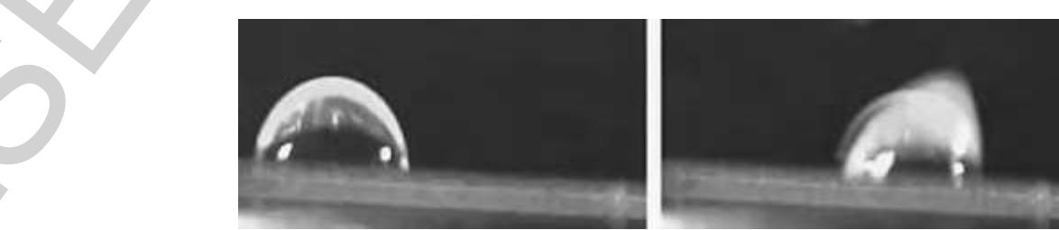
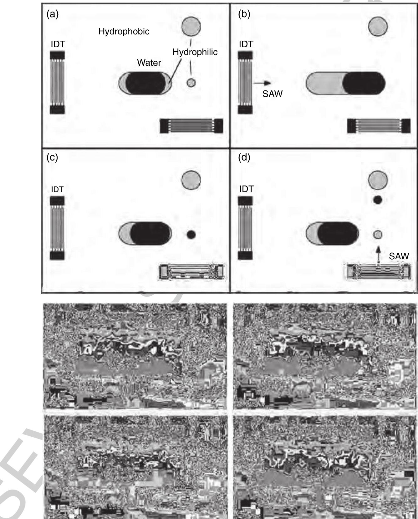
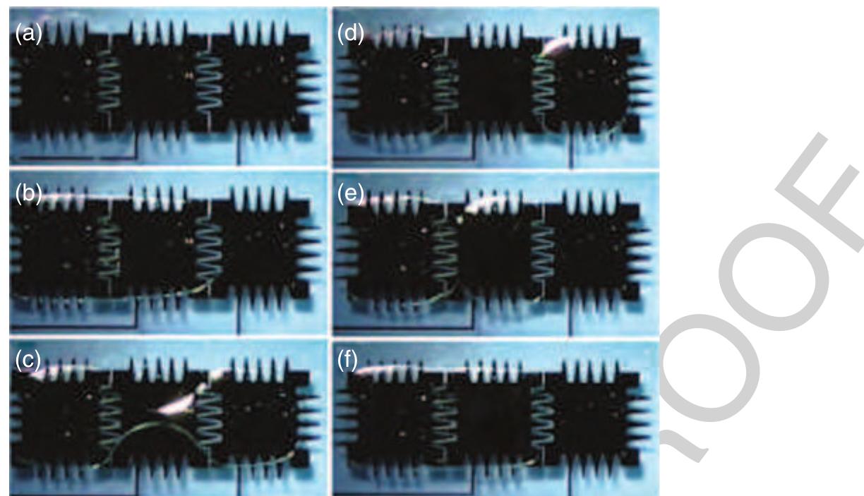
195 Figure 39. Acoustically driven metering process on the SAW platform. (a)-(d) Hydrophobic and hydrophilic areas are indicated in the schematic sketch on the top. First, the horizontally acting interdigital transducer (IDT) pushes the water dropletto the right across the hydrophobic substrate. After the actuation, the droplet withdraws meanwhile separating a small liquid volume, which remains at the small hydrophilic spot, as depicted in (c). In the last step, this metered liquid portion is pushed upward toward another hydrophilic zone. Corresponding photographs of the actual experiment are also depicted. (Source: Wixforth A, Strobl C, Gauer C, Toegl A, Scriba J, von Guttenberg Z 2004 Acoustic manipulation of small droplets. Anal. Bioanal. Chem. 379, 982-91. With kind permission of Springer Science and Business Media.) 985 Metering is accomplished by a combination of locally changed wetting properties of the surface and the actuation via SAW. One possible metering process is depicted in Figure 39. An initial water plug of approxi- mately 100 nl is placed on an oval hydrophilic zone on the chip surface (Figure 39(a)). After the first actuator (IDT) is activated, SAW propagate horizontally toward the liquid plug, pushing it to the right across another small hydrophilic metering spot (Figure 39(b)). After the actuation, the liquid volume withdraws to the hydrophilic regions on the chip, leaving behind a small metered liquid portion (Figure 39(c)). This dro- plet is subsequently moved upward by another IDT for
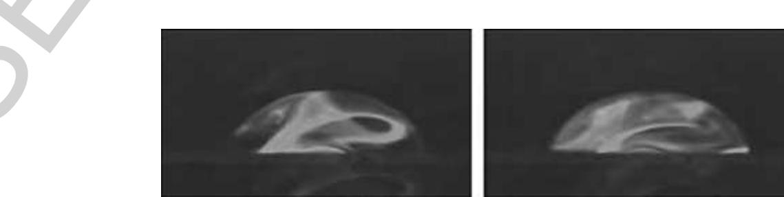
09 Figure 40 = Internal streaming is induced within an approximately 50-nI droplet, hit by SAW. The internal mixing process is ~ visualized by a fluorescent dye placed on the surface of the chip, which is dissolved by the SAW agitation. (Source: Wixforth A, Strobl C, Gauer C, Toegl A, Scriba J, von Guttenberg Z 2004 Acoustic manipulation of small droplets. Anal. Bioanal. Chem. 379, 982-91. With kind permission of Springer Science and Business Media.)
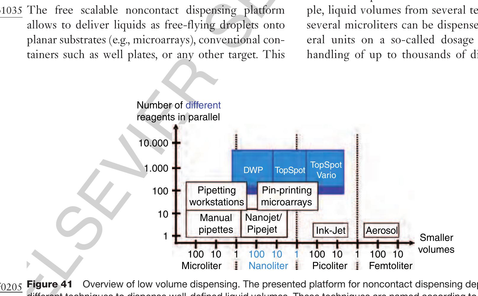
0445 2.13.7 Free Scalable Noncontact Dispensing
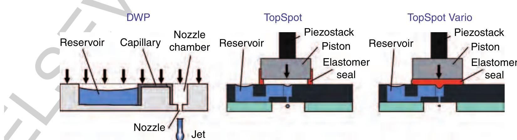
(9210 Figure 42 Dispensing well plate (DWP): Pressure-based actuation for dispensing from 10 nl up to several microliters; TopSpot®: pressure-based actuation for dispensing volumes in the lower nanoliter range; TopSpot® Vario: direct displacement principle via an elastomer for dispensing volumes from 50 to 1.000 pl. The basic structures like reservoirs, capillary p1 channel, nozzle chamber, and nozzles can be fabri- cated by different technologies using different materials. Dry etching of silicon (deep reactive ion 0725 etching, DRIE) (Steinert et a/ 2004), lithographic 0050 fabrication in SU-8 (Bohl et al 2005), and
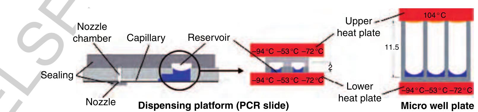
215 Figure 43 The nozzle and the reservoir opening are sealed for incubation and amplification. Thermal cycling within the thin ~ substrate (polymerase chain reaction (PCR) slide) requires an equal temperature for the upper and the lower plate at any time. Otherwise, inhomogeneous liquid temperatures can influence the assay performance. The engineering challenge in the microarray fab- p1 rication is to immobilize up to 1000 different analytes — as spots of approximately 1 nl volume, with a pitch of typically 500m and below, at high quality, high throughput, and low costs onto a substrate. One of the technical solutions to this problem is based on the TopSpot technology, a first application of the free 0250 scalable noncontact dispensing platform (Gutmann
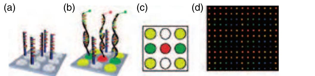
Figure 44 Illustration of the working principle of a DNA microarray. (a) Probe molecules are immobilized as different spots with a certain pitch on the solid surface; (b) a binding reaction takes place between the probe and the sample molecule if the chemical structures are complementary; (c) the fluorescent readout after the microarray experiment indicates positive binding events; and (d) fluorescent image from a real microarray experiment.
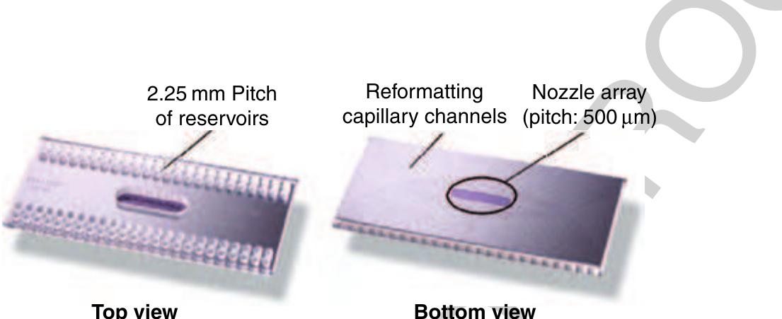
5 Figure 45 Picture of a 96 TopSpot® printhead. The top view shows the reservoirs that are filled via manual pipetting or lab ~ robots. The capillary channels that connect each reservoir with a certain.nozzle chamber ending up in an array of nozzles of pitch 500 um, a feature called reformatting, can be seen on the underside of the printhead (right).
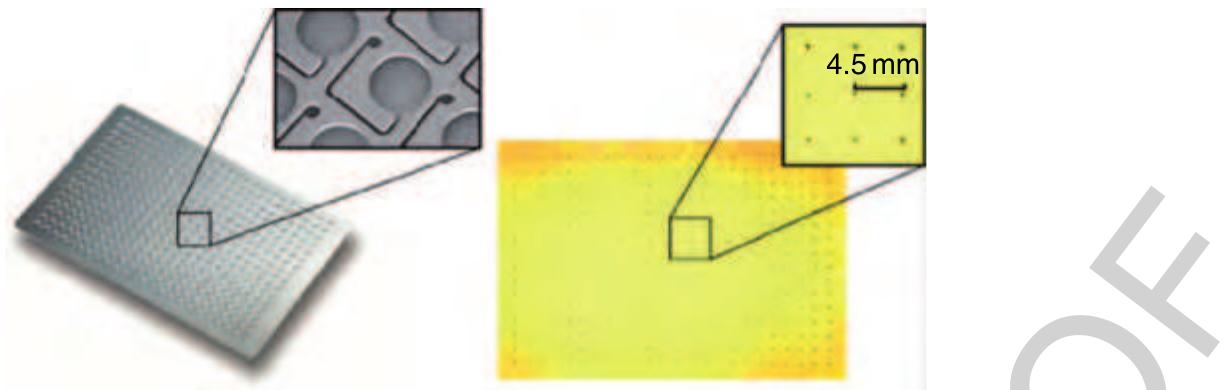
230 Figure 46 Picture of a 384 dispensing well plate (DWP) dispensing a chip micromachined in silicon. The 384 reservoirs are connected to 384 nozzle chambers next to the reservoirs via capillary channels. No format transformation (reformatting) but the metering and allocation of a defined liquid volume is accomplished within each of the 384 units. All these liquid portions are then transferred to another platform within the pneumatically driven noncontact dispensing process (Figure 42) or to a flat surface as depicted on the right.

Loading Preview
Sorry, preview is currently unavailable. You can download the paper by clicking the button above.
References (132)
- Abbott P-2006 East Windsor, NJ, USA, www.abbottpointofcare.com, accessed 2006 b0015
- Advalytix AG 2006 Brunnthal, Germany, www.advalytix.de
- Anderson N G 1969 Computer interfaced fast analyzers. Science 166, 317-24
- Andersson H, van den Berg A 2004 Lab-on-Chips for Cellomics, Micro and Nanotechnologies for Life Science. Kluwer Academic Publishers, Dordrecht, The Netherlands
- Anna S L, Bontoux N, Stone H A 2003 Formation of dispersions using ''flow focusing'' in microchannels. Appl. Phys. Lett. 82, 364-6
- Auroux P A, Iossifidis D, Reyes D R, Manz A 2002 Micro total analysis systems. 2. Analytical standard operations and applications. Anal. Chem. 74, 2637-52
- Berthier J, Clementz P, Raccurt O, Jary D, Claustre P, Peponnet C, Fouillet Y 2006 Computer aided design of an EWOD microdevice. Sens. Actuators A Phys. 127, 283-94
- Bohl B, Steger R, Zengerle R, Koltay P 2005 Multi-layer SU-8 lift-off technology for microfluidic devices. J. Micromech. Microeng. 15, 1125-30
- Brenner T, Glatzel T, Zengerle R, Ducre ´e J 2005 Frequency- dependent transversal flow control in centrifugal microfluidics. Lab Chip 5, 146-50
- Bringer M R, Gerdts C J, Song H, Tice J D, Ismagilov R F 2004 Microfluidic systems for chemical kinetics that rely on chaotic mixing in droplets. Philos. Trans. R. Soc. Lond. A Math. Phys. Eng. Sci. 362, 1087-104
- Burns M A, Johnson B N, Brahmasandra S N, Handique K, Webster J R, Krishnan M, Sammarco T S, Man P M, Jones D, Heldsinger D, Mastrangelo C H, Burke D T 1998 An integrated nanoliter DNA analysis device. Science 282, 484-7
- Burtis C A, Anderson N G, Mailen J C, Scott C D, Tiffany T O, Johnson W F 1972 Development of a miniature fast analyzer. Clin. Chem. 18, 753-61
- Chatterjee D, Hetayothin B, Wheeler A R, King D J, Garrell R L 2006 Droplet-based microfluidics with nonaqueous solvents and solutions. Lab Chip 6, 199-206
- Chen D L, Gerdts C J, Ismagilov R F 2005 Using microfluidics to observe the effect of mixing on nucleation of protein crystals. J. Am. Chem. Soc. 127, 9672-3
- Chen D L L, Ismagilov R F 2006 Microfluidic cartridges preloaded with nanoliter plugs of reagents: An alternative to 96-well plates for screening. Curr. Opin. Chem. Biol. 10, 226-31
- Chen H, Meiners J C 2004 Topologic mixing on a microfluidic chip. Appl. Phys. Lett. 84, 2193-5
- Cheng Y T, Lin L W, Najafi K 2001 A hermetic glass-silicon package formed using localized aluminum/silicon-glass bonding. J. Microelectromech. Syst. 10, 392-9
- Cho S K, Moon H J, Kim C J 2003 Creating, transporting, cutting, and merging liquid droplets by electrowetting-based actuation for digital microfluidic circuits. J. Microelectromech. Syst. 12, 70-80
- Chou H P, Unger M A, Quake S R 2001 A microfabricated rotary pump. Biomed. Microdevices 3, 323-30
- Clark T J, McPherson P H, Buechler K F 2002 The triage cardiac panel. Point Care 1, 42-6
- Delamarche E, Bernard A, Schmid H, Michel B, Biebuyck H 1997 Patterned delivery of immunoglobulins to surfaces using microfluidic networks. Science 276, 779-81
- b0120 deMello A J 2003 Microfluidics -DNA amplification moves on. Nature 422, 28-9
- Dendukuri D, Tsoi K, Hatton T A, Doyle P S 2005 Controlled synthesis of nonspherical microparticles using microfluidics. Langmuir 21, 2113-16
- Ducre ´e J, Zengerle R 2004 FlowMap -Microfluidics Roadmap for the Life Sciences. Books on Demand GmbH, Norderstedt, Germany b0135
- Ducre ´e J, Haeberle S, Brenner T, Glatzel T, Zengerle R 2005 Patterning of flow and mixing in rotating radial microchannels. Microfluidics Nanofluidics 2, 97-105
- Ducre ´e J, Brenner T, Haeberle S, Glatzel T, Zengerle R 2006 Multilamination of flows in planar networks of rotating microchannels. Microfluidics Nanofluidics 2, 78-84
- Duffy D C, McDonald J C, Schueller O J A, Whitesides G M 1998 Rapid prototyping of microfluidic systems in poly(dimethylsiloxane). Anal. Chem. 70, 4974-84
- Duffy D C, Gillis H L, Lin J, Sheppard N F Jr., Kellogg G J 1999 Microfabricated centrifugal microfluidic systems: Characterization and multiple enzymatic assays. Anal. Chem. 71, 4669-78
- Effenhauser C S, Manz A, Widmer H M 1993 Glass chips for high-speed capillary electrophoresis separations with submicrometer plate heights. Anal. Chem. 65, 2637-42
- Effenhauser C S, Bruin G J M, Paulus A, Ehrat M 1997 Integrated capillary electrophoresis on flexible silicone microdevices: Analysis of DNA restriction fragments and detection of single DNA molecules on microchips. Anal. Chem. 69, 3451-7 b0165
- Ehrfeld W, Golbig K, Hessel V, Lowe H, Richter T 1999 Characterization of mixing in micromixers by a test reaction: Single mixing units and mixer arrays. Ind. Eng. Chem. Res. 38, 1075-82
- Ekstrand G, Thorsen T 2005 Liquid router. US 2005/0141344 A1 b0175
- Ekstrand G, Holmquist C, O ¨rlefors A E, Hellman B, Larsson A, Andersson P 2000 Microfluidics in a rotating CD. In: Van den Berg A, Olthius W, and Bergveld P (eds.) Proc. Micro Total Analysis Systems 2000, Enschede, The Netherlands, pp. 311-14 b0180
- Erickson D 2005 Towards numerical prototyping of labs-on-chip: Modeling for integrated microfluidic devices. Microfluidics Nanofluidics 1, 301-18
- Fredrickson C K, Fan Z H 2004 Macro-to-micro interfaces for microfluidic devices. Lab Chip 4, 526-33
- Fu A Y, Spence C, Scherer A, Arnold F H, Quake S R 1999 A microfabricated fluorescence-activated cell sorter. Nat. Biotechnol. 17, 1109-11
- Garstecki P, Gitlin I, DiLuzio W, Whitesides G M, Kumacheva E, Stone H A 2004 Formation of monodisperse bubbles in a microfluidic flow-focusing device. Appl. Phys. Lett. 85, 2649-51 b0205
- Garstecki P, Fischbach M A, Whitesides G M 2005a Design for mixing using bubbles in branched microfluidic channels. Appl. Phys. Lett. 86, 244108
- Garstecki P, Stone H A, Whitesides G M 2005b Mechanism for flow-rate controlled breakup in confined geometries: A route to monodisperse emulsions. Phys. Rev. Lett. 94, 164501
- Gascoyne P R C, Vykoukal J V, Schwartz J A, Anderson T J, Vykoukal D M, Current K W, McConaghy C, Becker F F, Andrews C 2004 Dielectrophoresis-based programmable fluidic processors. Lab Chip 4, 299-309
- Geschke O, Klank H, Telleman P 2004 Microsystem Engineering of Lab-on-a-Chip Devices. Wiley-VCH, Weinheim b0225
- Goettsche T, Wolff A 2006 IntelliDrug -An integrated intelligent oral drug delivery system. mst-news 06, 36-7 b0230
- Gravesen P, Braneberg J, Jensen O S 1993 Microfluidics -A review. J. Micromech. Microeng. 3, 168-82
- Grumann M, Geipel A, Riegger L, Zengerle R, Ducre ´e J 2005 Batch-mode mixing on centrifugal microfluidic platforms. Lab Chip 5, 560-5
- Gunther A, Khan S A, Thalmann M, Trachsel F, Jensen K F 2004 Transport and reaction in microscale segmented gas-liquid flow. Lab Chip 4, 278-86
- Gunther A, Jhunjhunwala M, Thalmann M, Schmidt M A, Jensen K F 2005 Micromixing of miscible liquids in segmented gas- liquid flow. Langmuir 21, 1547-55
- Guttenberg Z, Muller H, Habermuller H, Geisbauer A, Pipper J, Felbel J, Kielpinski M, Scriba J, Wixforth A 2005 Planar chip device for PCR and hybridization with surface acoustic wave pump. Lab Chip 5, 308-17
- GYROS AB 2006 Uppsala, Sweden, www.gyros.com accessed 2006
- Haeberle S, Brenner T, Schlosser H P, Zengerle R, Ducre ´e J 2005 Centrifugal micromixer. Chem. Eng. Tech. 28, 613-16
- Haeberle S, Brenner T, Zengerle R, Ducree J 2006a Centrifugal extraction of plasma from whole blood on a rotating disk. Lab Chip 6, 776-81
- Haeberle S, Naegele L, Zengerle R, Ducre ´e J 2006b A Digital Centrifugal Droplet Switch For Routing of Liquids. In: Kitamori T, Fujita H, Hasebe S (eds), Proceedings of mTAS 2006, November 5-9, Tokyo, Japan, pp. 570-2.
- Haeberle S, Zengerle R, Ducre ´e J 2007 Centrifugal generation and manipulation of droplet emulsions. Microfluidics Nanofluidics 3, 65-75
- Hansen C, Quake S R 2003 Microfluidics in structural biology: Smaller, fasterÁ Á Á better. Curr. Opin. Struct. Biol. 13, 538-44
- Hansen C L, Skordalakes E, Berger J M, Quake S R 2002 A robust and scalable microfluidic metering method that allows protein crystal growth by free interface diffusion. Proc. Natl. Acad. Sci. USA 99, 16531-6
- Harrison D J, Manz A, Fan Z H, Ludi H, Widmer H M 1992 Capillary electrophoresis and sample injection systems integrated on a planar glass chip. Anal. Chem. 64, 1926-32
- Harrison D J, Fluri K, Seiler K, Fan Z H, Effenhauser C S, Manz A 1993 Micromachining -A miniaturized capillary electrophoresis-based chemical-analysis system on a chip. Science 261, 895-7
- He M Y, Edgar J S, Jeffries G D M, Lorenz R M, Shelby J P, Chiu D T 2005 Selective encapsulation of single cells and subcellular organelles into picoliter-and femtoliter-volume droplets. Anal. Chem. 77, 1539-44
- de Heij B, Steinert C, Sandmaier H, Zengerle R 2003 A tunable and highly-parallel picolitre-dispenser based on direct liquid displacement. Sens. Actuators A Phys. 103, 88-92
- de Heij B, Daub M, Gutmann O, Niekrawietz R, Sandmaier H, Zengerle R 2004 Highly parallel dispensing of chemical and biological reagents. Anal. Bioanal. Chem. 378, 119-22
- Hessel V, Hardt S, Lowe H, Schonfeld F 2003 Laminar mixing in different interdigital micromixers: I. Experimental characterization. AIChE J. 49, 566-77
- Hessel V, Lowe H, Schonfeld F 2005 Micromixers -A review on passive and active mixing principles. Chem. Eng. Sci. 60, 2479-501
- Honda N, Lindberg U, Andersson P, Hoffman S, Takei H 2005 Simultaneous multiple immunoassays in a compact disc- shaped microfluidic device based on centrifugal force. Clin. Chem. 51, 1955-61
- Hong J W, Quake S R 2003 Integrated nanoliter systems. Nat. Biotechnol. 21, 1179-83
- Hong J W, Studer V, Hang G, Anderson W F, Quake S R 2004 A nanoliter-scale nucleic acid processor with parallel architecture. Nat. Biotechnol. 22, 435-9
- Hosokawa K, Fujii T, Endo I 1999 Handling of picoliter liquid samples in a poly(dimethylsiloxane)-based microfluidic device. Anal. Chem. 71, 4781-5
- Huang L R, Cox E C, Austin R H, Sturm J C 2004 Continuous particle separation through deterministic lateral displacement. Science 304, 987-90
- Jandik P, Weigl B H, Kessler N, Cheng J, Morris C J, Schulte T, Avdalovic N 2002 Initial study of using a laminar fluid diffusion interface for sample preparation in high-performance liquid chromatography. J. Chromatogr. A 954, 33-40 b0375
- Jiang F, Drese K S, Hardt S, Kupper M, Schonfeld F 2004 Helical flows and chaotic mixing in curved micro channels. AIChE J. 50, 2297-305
- Joanicot M, Ajdari A 2005 Applied physics -Droplet control for microfluidics. Science 309, 887-8
- Johnson T J, Ross D, Locascio L E 2002 Rapid microfluidic mixing. Anal. Chem. 74, 45-51
- Kamholz A E 2004 Proliferation of microfluidics in literature and intellectual property. Lab Chip 4, 16N-20N
- Khan S A, Gunther A, Schmidt M A, Jensen K F 2004 Microfluidic synthesis of colloidal silica. Langmuir 20, 8604-11
- Knight J B, Vishwanath A, Brody J P, Austin R H 1998 Hydrodynamic focusing on a silicon chip: Mixing nanoliters in microseconds. Phys. Rev. Lett. 80, 3863-6 b0405
- Kobayashi I, Mukataka S, Nakajima M 2005 Effects of type and physical properties of oil phase on oil-in-water emulsion droplet formation in straight-through microchannel emulsification, experimental and CFD studies. Langmuir 21, 5722-30
- Koltay P, Kalix J, Zengerle R 2004a Theoretical evaluation of the dispensing well plate method (DWP part II). Sens. Actuators A Phys. 116, 472-82
- Koltay P, Steger R, Bohl B, Zengerle R 2004b The dispensing well plate: A novel nanodispenser for the multiparallel delivery of liquids (DWP Part I). Sens. Actuators A Phys. 116, 483-91
- Kopp M U, de Mello A J, Manz A 1998 Chemical amplification: Continuous-flow PCR on a chip. Science 280, 1046-8 b0425
- Lai S, Wang S, Luo J, Lee L J, Yang S T, Madou M J 2004 Design of a compact disk-like microfluidic platform for enzyme- linked immunosorbent assay. Anal. Chem. 76, 1832-7 b0430
- Laser D J, Santiago J G 2004 A review of micropumps. J. Micromech. Microeng. 14, R35-64
- Le H P 1998 Progress and trends in ink-jet printing technology. J. Imaging Sci. Technol. 42, 49-62
- Lee G B, Hung C I, Ke B J, Huang G R, Hwei B H 2001a Micromachined pre-focused 1ÂN flow switches for continuous sample injection. J. Micromech. Microeng. 11, 567-73
- Lee G B, Hwei B H, Huang G R 2001b Micromachined pre- focused MÂN flow switches for continuous multi-sample injection. J. Micromech. Microeng. 11, 654-61
- Lee J, Kim C J 2000 Surface-tension-driven microactuation based on continuous electrowetting. J. Microelectromech. Syst. 9, 171-80
- Lee J, Moon H, Fowler J, Schoellhammer T, Kim C J 2002 Electrowetting and electrowetting-on-dielectric for microscale liquid handling. Sens. Actuators A Phys. 95, 259-68
- Li P C H 2006 Microfluidic Lab-on-a-Chip for Chemical and Biological Analysis and Discovery. Taylor & Francis Group, Boca Raton, FL
- Link D R, Anna S L, Weitz D A, Stone H A 2004 Geometrically mediated breakup of drops in microfluidic devices. Phys. Rev. Lett. 92, 054503
- Lion N, Rohner T C, Dayon L, Arnaud I L, Damoc E, Youhnovski N, Wu Z Y, Roussel C, Josserand J, Jensen H, Rossier J S, Przbylski M, Girault H H 2003 Microfluidic systems in proteomics. Electrophoresis 24, 3533-62
- Liu J, Hansen C, Quake S R 2003 Solving the ''world-to-chip'' interface problem with a microfluidic matrix. Anal. Chem. 75, 4718-23
- Lotters J C, Olthuis W, Veltink P H, Bergveld P 1997 The mechanical properties of the rubber elastic polymer polydimethylsiloxane for sensor applications. J. Micromech. Microeng. 7, 145-7
- Madou M, Kellogg G J 1998 The LabCD: A centrifuge-based microfluidic platform for diagnostics. Proc. SPIE 3259, 80-93, Systems and technologies for clinical diagnostics and drug discovery
- Madou M, Lee J, Daunert S, Lai S, Shih C-H 2001 Design and fabrication of CD-like microfluidic platforms for diagnostics: Microfluidic functions. Biomed. Microdevices 3, 245-54
- Manz A, Graber N, Widmer H M 1990a Miniaturized total chemical-analysis system -A novel concept for chemical sensing. Sens. Actuators B Chem. 1, 244-8
- Manz A, Miyahara Y, Miura J, Watanabe Y, Miyagi H, Sato K 1990b Design of an open-tubular column liquid chromatograph using silicon chip technology. Sens. Actuators B Chem. 1, 249-55
- Manz A, Harrison D J, Verpoorte E M J, Fettinger J C, Paulus A, Ludi H, Widmer H M 1992 Planar chips technology for miniaturization and integration of separation techniques into monitoring systems -Capillary electrophoresis on a chip. J. Chromatogr. 593, 253-8
- Marcus J S, Anderson W F, Quake S R 2006a Microfluidic single-cell mRNA isolation and analysis. Anal. Chem. 78, 3084-9
- Marcus J S, Anderson W F, Quake S R 2006b Parallel picoliter RT-PCR assays using microfluidics. Anal. Chem. 78, 956-8
- Marko-Varga G, Nilsson J, Laurell T 2003 New directions of miniaturization within the proteomics research area. Electrophoresis 24, 3521-32
- Martin K, Henkel T, Baier V, Grodrian A, Schon T, Roth M, Kohler J M, Metze J 2003 Generation of larger numbers of separated microbial populations by cultivation in segmented-flow microdevices. Lab Chip 3, 202-7
- de Mello A J, Beard N 2003 Dealing with 'real' samples: Sample pre-treatment in microfluidic systems. Lab Chip 3, 11N-19N
- Mugele F, Baret J C 2005 Electrowetting: From basics to applications. J. Phys. Condens. Matter 17, R705-74
- Mugele F, Klingner A, Buehrle J, Steinhauser D, Herminghaus S 2005 Electrowetting: A convenient way to switchable wettability patterns. J. Phys. Condens. Matter 17, S559-76
- Nguyen N T, Wereley S T 2002 Fundamentals and Applications of Microfluidics. Artech House Books, Boston, MA
- Nguyen N T, Wu Z G 2005 Micromixers -A review. J. Micromech. Microeng. 15, R1-16
- Nisisako T, Torii T, Higuchi T 2002 Droplet formation in a microchannel network. Lab Chip 2, 24-6
- Oh K W, Ahn C H 2006 A review of microvalves. J. Micromech. Microeng. 16, R13-39
- Okushima S, Nisisako T, Torii T, Higuchi T 2004 Controlled production of monodisperse double emulsions by two-step droplet breakup in microfluidic devices. Langmuir 20, 9905-8
- Oosterbroek R E, van den Berg A 2003 Lab-on-a-Chip: Miniaturized Systems for (Bio)Chemical Analysis and Synthesis. Elsevier Science, Amsterdam
- Paik P, Pamula V K, Fair R B 2003a Rapid droplet mixers for digital microfluidic systems. Lab Chip 3, 253-9 b0585
- Paik P, Pamula V K, Pollack M G, Fair R B 2003b Electrowetting- based droplet mixers for microfluidic systems. Lab Chip 3, 28-33 b0590
- Pollack M G, Fair R B, Shenderov A D 2000 Electrowetting- based actuation of liquid droplets for microfluidic applications. Appl. Phys. Lett. 77, 1725-6 b0595
- Pollack M G, Shenderov A D, Fair R B 2002 Electrowetting- based actuation of droplets for integrated microfluidics. Lab Chip 2, 96-101
- Quake S R, Scherer A 2000 From micro-to nanofabrication with soft materials. Science 290, 1536-40
- Raschke G 2005 Molekulare Erkennung mit einzelnen Gold- Nanopartikeln. PhD-thesis, TU Muenchen b0610
- Ren H, Fair R B, Pollack M G 2004 Automated on-chip droplet dispensing with volume control by electro-wetting actuation and capacitance metering. Sens. Actuators B Chem. 98, 319-27
- Reyes D R, Iossifidis D, Auroux P A, Manz A 2002 Micro total analysis systems. 1. Introduction, theory, and technology. Anal. Chem. 74, 2623-36
- Roach L S, Song H, Ismagilov R F 2005 Controlling nonspecific protein adsorption in a plug-based microfluidic system by controlling interfacial chemistry using fluorous-phase surfactants. Anal. Chem. 77, 785-96
- Roche 2006 Basel, CH, www.roche.com, accessed 2006 b0630
- Salemme F R 1972 Free interface diffusion technique for crystallization of proteins for X-ray crystallography. Arch. Biochem. Biophys. 151, 533-9
- Schembri C T, Ostoich V, Lingane P J, Burd T L, Buhl S N 1992 Portable simultaneous multiple analyte whole-blood analyzer for point-of-care testing. Clin. Chem. 38, 1665-70 b0640
- Schembri C T, Burd T L, Kopfsill A R, Shea L R, Braynin B 1995 Centrifugation and capillarity integrated into a multiple analyte whole-blood analyzer. J. Automatic Chem. 17, 99-104 b0645
- Schonfeld F, Hessel V, Hofmann C 2004 An optimised split- and-recombine micro-mixer with uniform 'chaotic' mixing. Lab Chip 4, 65-9
- Schwartz J A, Vykoukal J V, Gascoyne P R C 2004 Droplet- based chemistry on a programmable micro-chip. Lab Chip 4, 11-17 b0655
- Shestopalov I, Tice J D, Ismagilov R F 2004 Multi-step synthesis of nanoparticles performed on millisecond time scale in a microfluidic droplet-based system. Lab Chip 4, 316-21
- Shoji S, Esashi M 1994 Microflow devices and systems. J. Micromech. Microeng. 4, 157-71
- Shoji S, Esashi M, Matsuo T 1988 Prototype miniature blood- gas analyzer fabricated on a silicon-wafer. Sens. Actuators 14, 101-7
- Sia S K, Whitesides G M 2003 Microfluidic devices fabricated in poly(dimethylsiloxane) for biological studies. Electrophoresis 24, 3563-76
- Song H, Ismagilov R F 2003 Millisecond kinetics on a microfluidic chip using nanoliters of reagents. J. Am. Chem. Soc. 125, 14613-19
- Song H, Bringer M R, Tice J D, Gerdts C J, Ismagilov R F 2003a Experimental test of scaling of mixing by chaotic advection in droplets moving through microfluidic channels. Appl. Phys. Lett. 83, 4664-6
- Song H, Tice J D, Ismagilov R F 2003b A microfluidic system for controlling reaction networks in time. Angew. Chem. Int. Ed. 42, 768-72
- Song Y J, Zhao T S 2001 Modelling and test of a thermally- driven phase-change nonmechanical micropump. J. Micromech. Microeng. 11, 713-19
- SpinX Technologies 2006 Geneva, Switzerland, www.spinx-technologies.com accessed 2006
- Squires T M, Quake S R 2005 Microfluidics: Fluid physics at the nanoliter scale. Rev. Mod. Phys. 77, 977-1026