Characterization and permeation properties of ZSM-5 tubular membranes (original) (raw)
Abstract
ZSM-5 zeolite membranes with reproducible properties were prepared by in-situ synthesis on porous α- and γ-alumina tubular supports and characterized by XRD, SEM and electron microprobe analysis. Single-gas permeances for H2, CH4, N2, CO2, n-butane, and i-butane increase over some temperature range, but some gases exhibit maxima or minima. The highest ideal selectivities at room temperature are 299 for N2/SF6, 392 for H2/n-butane, and 2,820 for H2/i-butane. These membranes can separate n-butane/i-butane, H2/n-butane and H2/i-butane mixtures. All n-butane/i-butane separation selectivities have maxima as a function of temperature and are higher than ideal selectivities because n-butane inhibits i-butane permeation. Thus, separation is not by size selectivity, but is due to pore blocking. Temperature depenencies of single-gas permeances and separation selectivities depend strongly on the location of zeolite crystals and the location is determined by preparation procedure. Ideal selectivities also depend strongly on the preparation procedure. When the zeolite forms a continuous layer on the inside surface of the support tubes, pure i-butane permeates faster than pure n-butane so that the single-gas permeances are not determined just by molecular size. The i-butane permeance also increases much more with temperature than the n-butane permeance. The permeation behavior may be the result of permeation through nonzeolitic pores in parallel with zeolite pores. When zeolite crystals are dispersed throughout the pores of α-alumina supports, permeances are lower and gas permeation and separation properties are quite different. Ideal selectivities are lower, pure n-butane permeates faster than i-butane, and the permeances increase much less with temperature. Separation selectivities are lower but can be maintained to higher temperatures.
Figures (27)
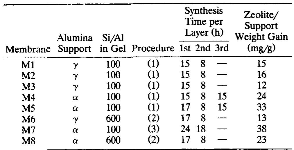
Table 1. Synthesis Conditions and Properties of Membranes M1 to M8


Table 2. Properties of Membranes Prepared by Procedure 1 with a Si/Al Ratio in the Gel of 100 A continuous ZSM-5 layer, which is approximately 20-25 um thick, is also present on top of the a-alumina support, as shown in Figure 2c for membrane M14, which was grown by procedure 1. Membranes M9 and M14 were made with the same procedure and the same gel, but on different supports and some of their properties are in Table 2. An intergrown layer of ZSM-S crystals formed on the surfaces of both y- and a-alumina supports when procedure 1 was used with a gel with high Al content. The crystals are smaller (about 2-3 ym) for membrane M14 (Figure 2d) than for membrane M9. The Si and Al concentrations were measured by EPMA as a function of distance from the inner surface of membrane M9, which was prepared by procedure 1 on a y-alumina sup- port. The cross section was analyzed at a 40° angle from the perpendicular to the surface. As shown in Figure 3a, the av-

“igure 2. SEM photographs of (a) cross section of membrane M9, made on y -alumina; (b) top view of membrane M9; (c) cross section of membrane M14, made on a -alumina; (d) top view of membrane M14; (e) cross section of membrane M7, made on a -alumina; (f) top view of membrane M7; (g) cross section of mem- brane M7, taken 150 4m from the surface.

erage Si/Al ratio was 32+15 (standard deviation) between the surface and 37 wm deep into the zeolite layer. The irreg- ular nature of the surface, shown in Figure 2a, is probably responsible for the scatter in Figure 3a (the Si/Al ratio ranged between 10 and 58). Because the microprobe measurements were made at an angle, this 37-4m distance corresponds to a zeolite layer thickness of 28 ym, which is in good agreement with thickness estimated from the SEM photograph in Figure 2a. It is also in reasonable agreement with the rough estimate of 45 wm made from the weight gain. Further from the sur-

* Milligrams (mg) of zeolite per g of support. Table 3. Membranes Prepared by Procedure 1 with Different Gels


Table 4. Permeances and Ideal Selectivities at 300 K for Membranes M1 to M8 To demonstrate the reproducibility of the membrane preparation, eleven membranes prepared by procedure 1 are compared in Table 2. The first seven of these membranes were prepared by depositing two layers of zeolite onto y- alumina supports, and the average weight gain for these two layers is 15.1+1.8 mg of zeolite per gram of membrane. The N, permeances are also similar for these seven membranes (8.7+1.1 mol:s~'-m~?-Pa~'), The N,/SF, ideal selectivi- ties showed more variation since they are so sensitive to vari- ations in the small permeances of SF,. The average N,/SF, ideal selectivity is 199 + 64 for the seven membranes that have two layers on y-alumina, and for the eleven membranes in Table 2 the average N,/SF, ratio is 214+57. Thus, the preparation of ZSM-5 membranes on tubular supports is quite reproducible, and procedure 1 appears to make membranes with both high permeances for light gases and high ideal se- lectivities. Also, for the membranes in Table 2, addition of a third or fourth layer does not appear to change these mem- brane properties much; for example, the N, permeance is not lower. Py, py ea eT ee, Se oe, ene ee Sa

ne ee ne nn IEE EE ELE NE For membranes that were prepared by procedures 2 and 3 on a-alumina supports (membranes M7 and M8), the single- gas permeances exhibited quite different behavior from membranes prepared by procedure 1. As shown in Table 4, the N,/SF, ideal selectivities at room temperature are a fac- tor of 10 or more smaller for membranes M7 and M8 than for membranes M1-MS, and the H,/i-butane ideal selectivi- ties are 1-2 orders of magnitude smaller. The n-butane/i- butane ideal selectivities are also small at room temperature, but n-butane permeated faster than i-butane for membranes M7 and M8 between 300 and 540 K. For membrane M7, which was prepared by procedure 3, the n-butane permeance exhib- ited a distinct maximum near 450 K, while the i-butane permeance increased less than a factor of 3 between 300 and 550 K (Figure 7). Membrane M8 also appeared to have a maximum in n-butane permeance, but it was at the highest temperature studied, as shown in Figure 8. The butane per- Single-gas permeances for membrane M1 increased with temperature for H,, n-butane, and i-butane, as shown in Figure 5. The butane permeances increased much faster than the H, permeance, as the temperature increased so that the

Table 5. n-C,H,,/i-C 4H Selectivities for Membranes Mi to M8

Separations of 50/50 n-butane/i-butane feed mixtures were measured for some membranes as a function of temperature.


Solid lines: 50/50 n-butane/i-butane mixture; dashed lines: single-gas permeances.

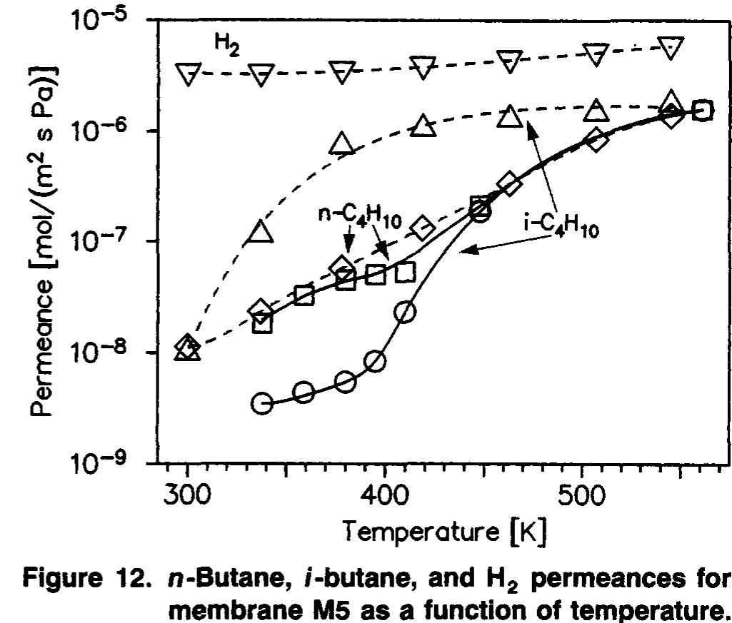
The butane permeances had similar temperature depend- encies for membranes prepared by procedure 1 on a-alumina supports. Figure 12 shows the single-gas (dashed lines) and mixture (solid lines) permeances for membrane MS. The n- butane permeance was not changed much by the presence of i-butane, but the i-butane permeance decreased by as much as 2 orders of magnitude in the presence of n-butane. Thus, although the n-butane/i-butane ideal selectivity was signifi- cantly less than one, the separation selectivity was greater than one until at least 410 K. At 450 K and above, no separa- tions were obtained. Note that the single-gas behavior in Fig- ure 12 is quite similar to that in Figure 10, with i-butane permeating faster than n-butane and also increasing faster In contrast to the n-butane/i-butane behavior for mem- branes prepared by procedure 1, membranes M7 and M8, which were supported on a-alumina but were not prepared by procedure 1, showed different behavior with temperature. Even though the N, permeances were lower for membranes M7 and M8 than for membranes M1-MS, the i-butane per- meances in the mixtures were higher at low temperatures for membranes M7 and M8. More significantly, as shown in Fig- ures 13 and 14, the i-butane permeances did not change as


Solid lines: 50/50 n-butane/i-butane mixture; dashed lines. single-gas permeances.


The H.,/n-butane ideal selectivity was only 15 at room temperature for membrane M8. In a mixture, n-butane per- meated faster than H, over a much wider temperature range

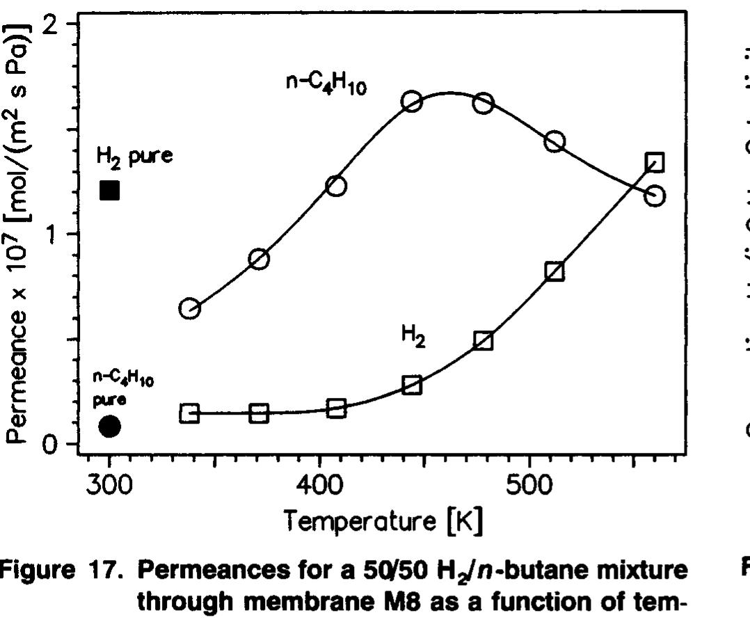

(340-540 K) for this membrane, as shown in Figure 17. n- Butane probably permeates faster than H, at room tempera- ture in the mixture, but measurements were not made below 340 K because of the low fluxes. The maximum n-butane/H, separation selectivity for membrane M&8 is 7.3 at 408 K. A comparison of Figure 8 (single-gas permeances) and Figure 17 (permeances in mixtures) shows that H, permeance was decreased by a factor of 9.2 at 338 K when n-butane was present. Discussion


Table 6. Comparison of Membrane Properties

Table 7. Comparations of H, Permeances and Ideal H,/n-C, Hj, and n-C,Hj9/i-C 4H 9 Selectivities

Loading Preview
Sorry, preview is currently unavailable. You can download the paper by clicking the button above.
References (25)
- Bai, C., M. D. Jia, J. L. Falconer, and R. D. Noble, "Preparation and Separation Properties of Silicalite Composite Membranes," .I. Memb. Sci., 105, 79 (1995).
- Bakker, W. J. W., K. Kapteijn, J. Poppe, and J. A. Moulijn, "Per- meation Characteristics of a Metal-supported Silicalite-1 Zeolite Membrane,"J. Memb. Sci., 117, 57 (1996).
- Funke, H. H., K. R. Fender, K. M. Green, J. L. Wilwerding, B. A. Sweitzer, J. L. Falconer, and R. D. Noble, "Influence of Adsorbed Molecules on the Permeation Properties of Silicalite Membranes," J . Memb. Sci. (1997a).
- Funke, H. H., A. M. Argo, J. L. Falconer, and R. D. Noble, "Sep- arations of Cyclic, Branched, and Linear Hydrocarbon Mixtures through Silicalite Membranes," 2nd. Eng. Chem. Res., 36, 137 (1997b).
- Funke, H. H., M. G. Kovalchick, J. L. Falconer, and R. D. Noble, "Separation of Hydrocarbon Isomer Vapors with Silicalite Zeolite Membranes," Znd. Eng. Chem. Res., 35, 1575 (1996a).
- Funke, H. H., A. M. Argo, C. D. Baertsch, J. L. Falconer, and R. D. Noble, "Separations of Close-Boiling Hydrocarbons with Silicalite Zeolite Membranes,"J. Chem. SOC. Farad. Trans., 92,2499 (1996b).
- Geus, E. R., M. J. den Exter, and H. van Bekkum, "Synthesis and Characterization of Zeolite (MFI) Membranes on Porous Ceramic Supports," J . Chem. SOC. Farad. Trans., 88, 3101 (1992).
- Giroir-Fendler, A., J. Peureux, H. Mozzanega, and J. A. Dalmon, "Characterization of a Zeolite Membrane for Catalytic Membrane Reactor Application," Stud. Surf. Sci. Cataf., 111, 127 (1996).
- Grose, R. W., and E. M. Flanigen, "Crystalline Silica," US. Patent No. 4,061,724 (1977).
- Jia, M. D., B. Chen, R. D. Noble, and J. L. Falconer, "Ceramic- Zeolite Composite Membranes and their Application for Separa- tion of Vapor/Gas Mixtures," J. Memb. Sci., 90, 1 (1994).
- Jia, M. D., K. V. Peinemann, and R. D. Behling, "Ceramic Zeolite Composite Membranes. Preparation, Characterization and Gas Permeation,'' J . Memb. Sci., 82, 15 (1993).
- Kapteijn, F., W. J. W. Bakker, J. van de Graaf, G. Zheng, J. Poppe, and J. A. Moulijn, "Permeation and Separation Behavior of a Sili- calite-1 Membrane," Cataf. Today, 25, 213 (1995).
- Kovalchick, M., J. Poshusta, R. D. Noble, and J. L. Falconer, in preparation (1997).
- Kusakabe, K., S. Yoneshige, A. Murata, and S. Morooka, "Mor- phology and Gas Permeance of ZSM-5-Type Zeolite Membrane Formed on a Porous a-Alumina Support Tube," J . Memb. Sci., 116, 39 (1996).
- Masuda, T., A. Sato, H. Hara, M. Kouono, and K. Hashimoto, "Pre- paration of a Dense ZSM-5 Zeolite Film on the Outer Surface of an Alumina Ceramic Filter," Appl. Catal., 111, 143 (1994).
- Matsukata, M., N. Nishiyama, and K. Ueyama, "Zeolitic Membrane Synthesized on a Porous Alumina Support," J . Chem. Soc., Chem. Commun., 339 (1994).
- Myatt, G. J., P. M. Budd, C. Price, and S. W. Cam, "Synthesis of a Zeolite NaA Membrane,"J. Muter. Chem., 2, 1103 (1992).
- Nishiyama, N., K. Ueyama, and M. Matsukata, " A Defect-free Mor- denite Membrane Synthesized by Vapor-phase Transport Method," J . Chem. Soc., Chem. Commun., 1967 (1995).
- Sano, T., Y. Kiyozumi, K. Maeda, M. Toba, S. Niwa, and F. Mizukami, "Synthesis and Characterization of Polycrystalline SAPO-5 Film," J . Mof. Catal., 77, L19 (1992a).
- Sano, T., F. Mizukami, H. Takaya, T. Mouri, and M. Watanabe, "Growth Process of ZSM-5 Zeolite Film," Buff. Chem. SOC. Jpn., 65, 146 (1992b).
- Shah, D. B., S. Chokchai-acha, and D. T. Hayhurst, "Measurements of Transport Rates of C4 Hydrocarbons across a Single-Crystal Sil- icalite Membrane," J . Chem. Soc. Farad. Trans., 89, 3161 (1993).
- Tsikoyiannis, J. G., and W. 0. Haag, "Synthesis and Characteriza- tion of a Pure Zeolitic Membrane," Zeolites, 12, 126 (1992).
- Vroon, Z. A. E. P., K. Keizer, M. J. Gilde, H. Verweij, and A. J. Burggraaf, "Transport of Alkanes Through Ceramic Thin Zeolite MFI Membranes,"J. Memb. Sci., 113, 293 (1996).
- Vroon, Z. A. E. P., "Synthesis and Transport Studies of Thin Ce- ramic Supported Zeolite (MFI) Membranes," PhD Thesis, Univ. of Twente, Twente, The Netherlands (1995).
- Yan, Y., M. E. Davis, and G. R. Gavalas, "Preparation of Zeolite ZSM-5 Membranes by In-Situ Crystallization on Porous a-A1203," 2nd. Eng. Chem. Res., 34, 1652 (1995).