European Research Infrastructure supporting Smart Grid Systems Technology Development , Validation and Roll Out Work Package 08 JRA 2-Co-Simulation based Assessment Methods Deliverable D 8 . 1 D-JRA 2 . 1 Simulator coupling and Smart Grid libraries (original) (raw)
Abstract
and Technology (NTNU) and jointly operated by SINTEF and NTNU. The laboratory has been recently refurbished and is under upgrade with state of the art solutions/technologies. The laboratory mainly consists of three platforms: the smart network testing facility, the smart house demonstration and the distributed energy storage infrastructure. Smart network testing facility: The core of the National Smart Grid Laboratory is the smart network testing facility. The facility can provide a flexible and reconfigurable electrical layout for conducting experiments at low voltage levels (e.g. 400 V AC or 800 V DC). The electrical system can be configured to represent a distribution or transmission grid with high penetration of renewable units including storage units and power electronics converters.
Figures (80)


Figure 3: AIT SmartEST facility The AIT SmartEST, located in Vienna, Austria, provides a multifunctional research, validation, and testing infrastructure allowing the testing of single devices as well as analysis of the interactions among multiple power system components — especially Distributed Energy Resource (DER)-based inverter systems — and the power grid under realistic, nearly real-world situations. The laboratory includes three configurable three-phase low-voltage grids; a high-bandwidth, programmable power grid simulator; several Photovoltaic (PV) array simulators; and an environmental test chamber for emulating various environmental conditions. This permits the validation and testing of DER-based inverter systems at full power under extreme temperature and humidity conditions and the investiga- tion of their interactions under various power grid conditions. The facility is capable of testing invert- ers, storage units, grid controllers, and Combined Heat and Power (CHP) units as well as charging stations/supply equipment for electric vehicles in the power range from a few kVA up to 1 MVA.

Figure 4: AIT SmartEST research and testing facility for smart grid systems and components

In addition, AIT SmartEST allows the real-time simulation of complex power grids and components as well as the coupling of this virtual environment with the laboratory grids. This kind of Hardware- in-the-Loop (HIL) setup lets researchers integrate real power system components into a virtual grid environment and test them as they interact with the grid under realistic conditions. Besides the HIL- based integration of power system components, Information and Communication Technology (ICT)/automation approaches, concepts, and developments can be integrated into the whole setup, allowing a comprehensive analysis of smart grid-related topics. The combination of a state-of-the- art testing infrastructure with HIL-based simulations (i.e., of the power system and ICT/automation infrastructure) provides cutting-edge testing capabilities for component manufacturers and network operators.

Designed as a pure low-voltage research and testing environment, all AC buses are rated for op- eration at voltages of up to 480 V (line to line). The laboratory itself is supplied from the local 20 kV medium-voltage power grid via two independent medium- and low-voltage (MV/LV) transformers. The test facility has been used for comprehensive performance testing of DER equipment as wel as qualification testing to national and international grid codes and standards based on the exten- sive range of accreditations held by AIT. Research on procedures for advanced interoperability testing of single as well as multiple DER units under different grid control schemes supports the integration of DERs into a future smart grid through standardized communication and coordination among generators, consumers, and storage units.

Smart Electricity Systems and Technologies Laboratory (SmartEST) — AI

Figure 7: CEA Ines (Le Bourget-du-Lac, France) The heart of the infrastructure is the hardware in the loop (HIL) simulator which allows the simula tion of any complex grid situation and which transforms a specific grid points into reality with the use of 45kVA three-phase power amplifier. This can be used to test specific components and the different control and management strategies. The hardware in the loop simulator is integrated ir the multi microgrid platform PRISMES, which covers the complete campus of INES. Single phase and three phase grids are available at the platform, which are completely independent allowinc running different projects in parallel.

\vailable devices which can be connected to this PRISMES platform are among others:


Figure 10: Facilities at CEA Ines

The already existing system of generators is expandable by incorporating the equipment of the adjacent laboratory, namely the RES & Hydrogen Technologies Integration Laboratory, of CRES. Thus, in the DER portfolio there can be inculed a set of hydrogen technology units, namely a 5-kW PEM fuel cell and one electrolyser capable of producing 0.5Nm*/hr which functions as a load to the system. Apart from that, the other consumers of the microgrid are a 13 kW resistor load bank, one capacitive load (2.5kVAr) and one reverse osmosis desalination unit (3.5 kW).
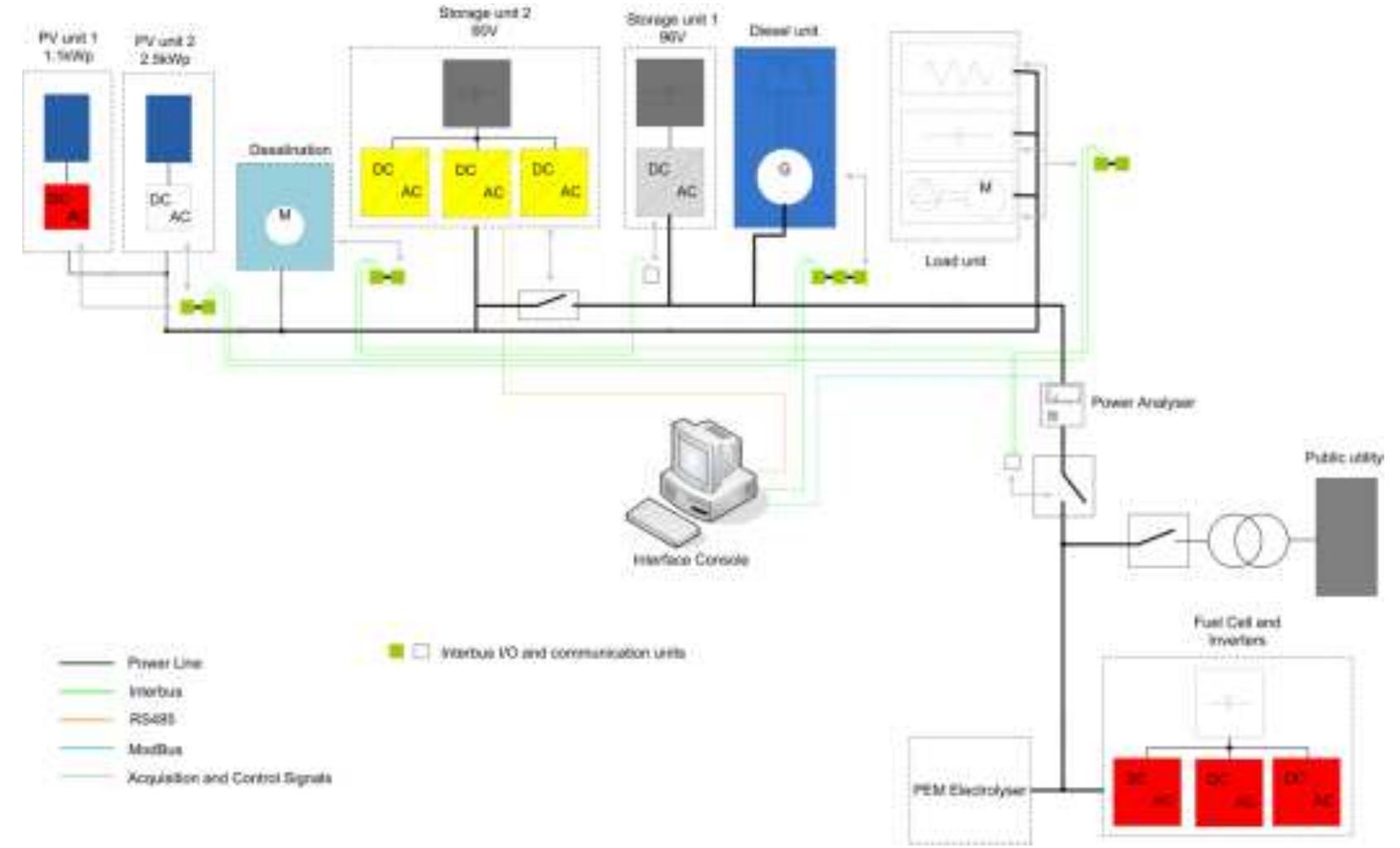

Figure 13: Snapshot of the main screen of the supervisory control application in DG-Lat


Figure 15: Programmable Grid simulator and load-bank control in DG-Lab

Figure 17: DG-Lab facilities } Services offered by the Research Infrastructure

Figure 16: Battery testers in DG-Lab

Figure 18: FPGL at DNV GL (Arnhem, the Netherlands)

Figure 19: Different AC power quality phenomena available at the FPGL infrastructure

Figure 20: Layout of the electrical grid in SYSLAB
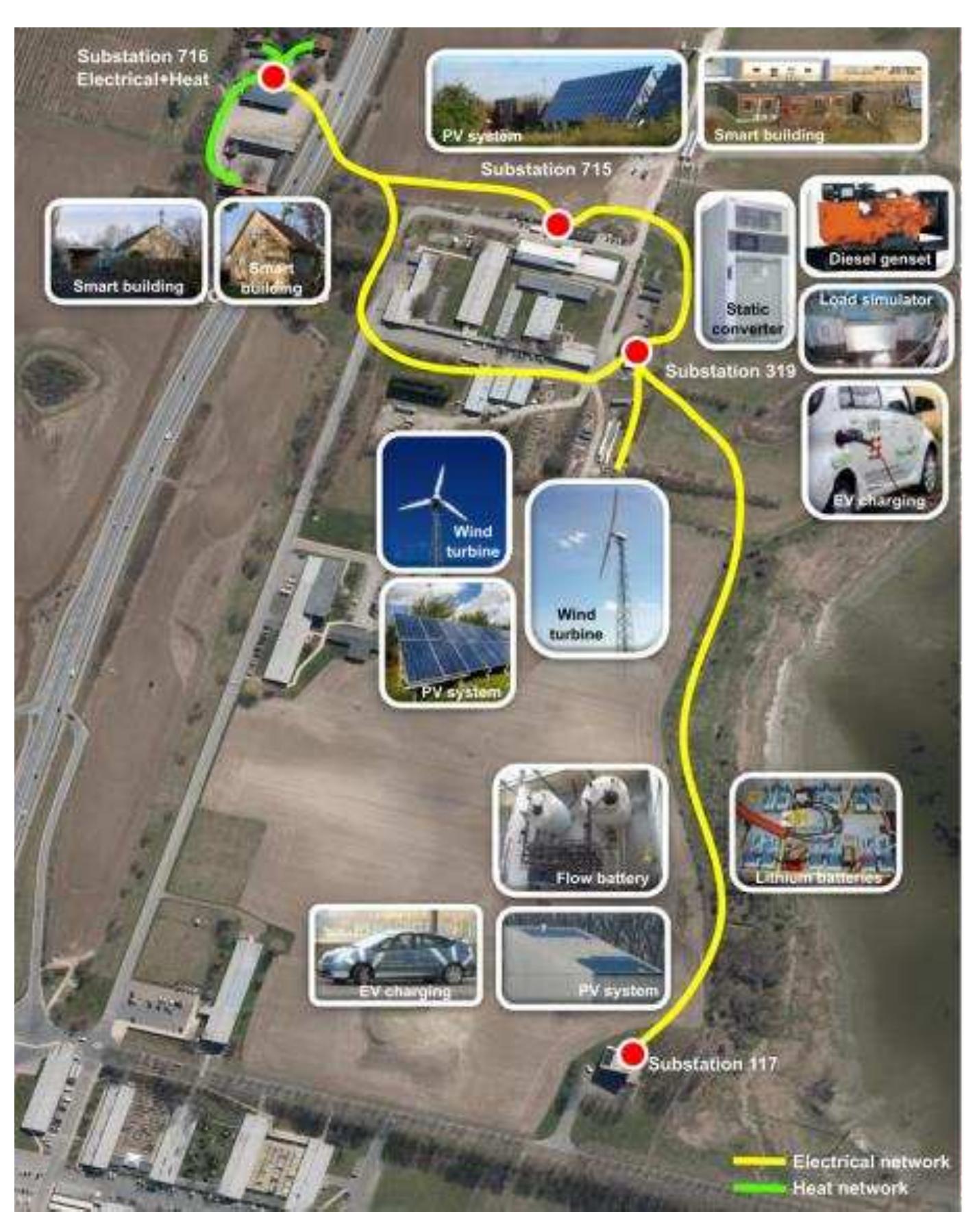
Figure 21: Overview of the SYSLAB facility on Riso campus


Figure 23: G2Elab facilities (Grenoble, France)


Figure 27: G2Elab facilities (Grenoble, France)


Figure 28: EESL Laboratory at ICCS-NTUA (Athens, Greece)

Figure 29: EESL Laboratory at ICCS-NTUA


Figure 34: The main building of IWES-SysTec with the labs SysTec PNI and SysTec TPE In the IWES-SysTec test center for smart grids and electromobility, Fraunhofer IWES is developing and testing new equipment and operation strategies for smart low and medium voltage grids. In addition, investigations regarding grid integration and grid connection of electric vehicles and their power generated from renewable energy sources as well as photovoltaic systems, wind energy plants, storage and hybrid systems are carried out under realistic conditions here. A large open-air ground of approx. 80,000 m? offers sufficient space and very good conditions for solar and wind energy. Furthermore, the open-air ground provides configurable distribution grid sectors (low and medium voltage.

Figure 35: View into the control room of the Lab SysTec PNI

Figure 36: Inside view into the Lab “SysTec PNI”

Figure 37: MV Equipment under test: Power transformer with OLTC

Website: Address:K6nigstor 59— 34119 Kassel, Germany Test Center for Smart Grids and Electromobility (IWES-SysTec) — Fraunhofer IWES

Figure 38: UDEX at ORMAZABAL Corporate Technology (Amorebieta, Spain) The UDEX management system (UMS) controls the operation of the infrastructure to run according to a certain strategy, physically connects/disconnects the elements, and changes the network to- pology, by means of fully automated operation. The facility allows the research and development ot the connection, integration and validation of new technologies, assessment of the impact on the network, and the investigation of operation of the complete network.


Figure 40: UDEX at ORMAZABAL Corporate Technology


Figure 44: OFFIS premises (Oldenburg, Germany) compliant IT integration of distributed producers and consumers, large and flexible distributed software architectures for business contexts within the energy domain, simulation, and intelligent data management. Transnational Access conditions offered by OFFIS


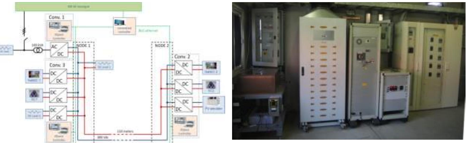
Figure 47: LV DC Microgrid at DER-TF
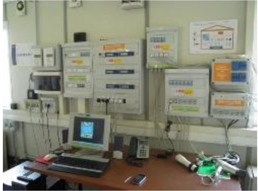
Figure 49: Domotic house at DER-TF

Figure 48: Face-to-Face convert- er at DER-TF


Figure 55: NSGL equipment at SINTEF
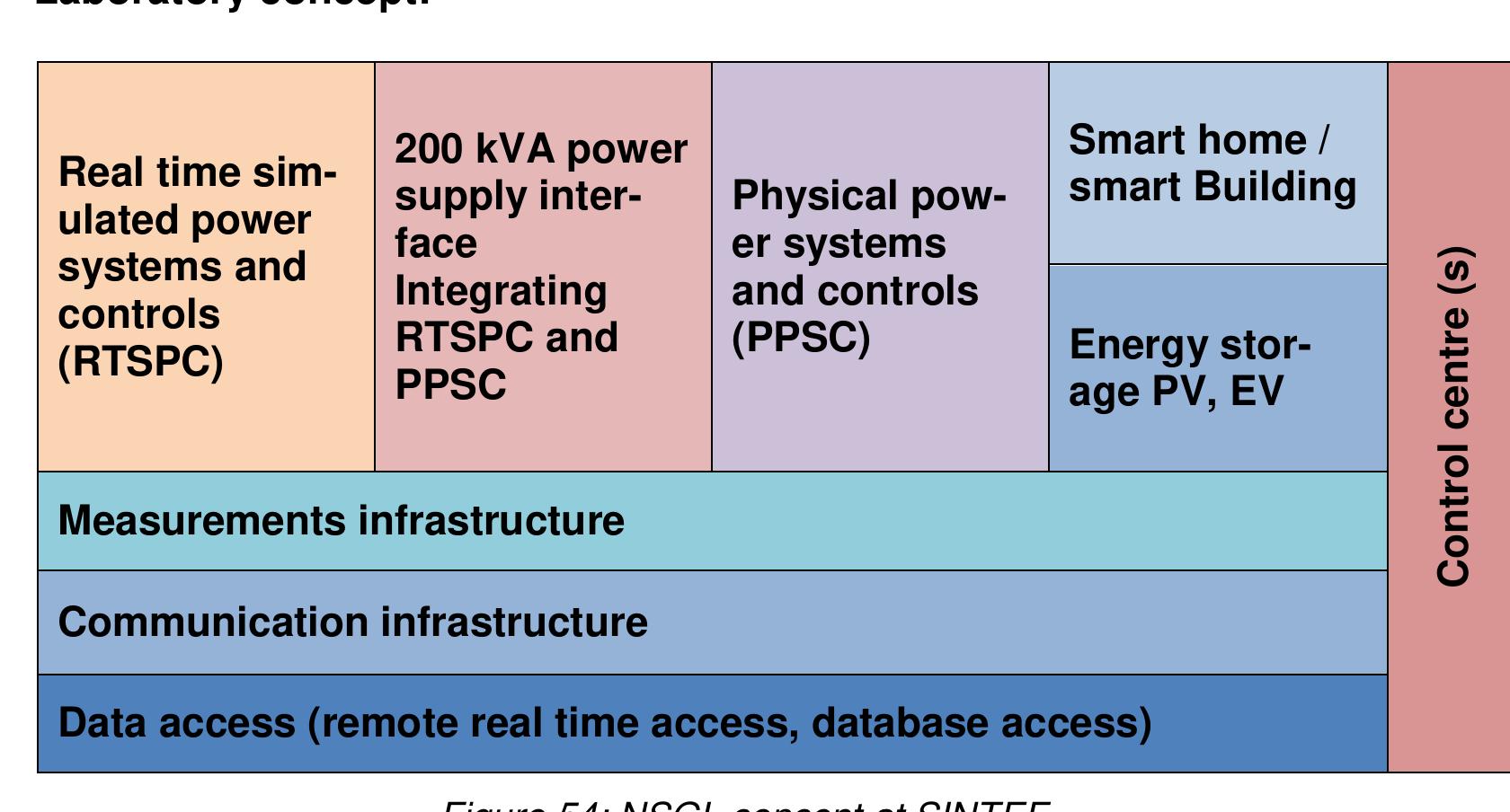

Figure 56: Microgrid of the Smart Grid Technologies Laboratory at TECNALIA (Derio, Spain) The core of the Smart Grid Technologies Laboratory (SGTL) is a low voltage three-phase mi- crogrid formed by different generation and storage devices and several loads, with a manageable power of around 200 kVA. Main elements of the microgrid are: generators (PV, diesel, wind tur- bine, etc.), network simulators, storage devices (flywheel, battery banks, ultracapacitor-based UPS, etc.), loads (resistive, inductive, capacitive, electronic loads), and power converters; a mi- crogrid management system controls the operation of the infrastructure to run according to certain strategy, physically connects/disconnects the elements, and changes the microgrid topology, by means of a switching cabinet. The facility allows the research and development on the connection, integration and validation of DER technologies, assessment of the impact on the network, and the investigation on operation and control strategies of the entire microgrid.

Figure 57: Electrical Vehicle platform at TECNALIA

Figure 58: Smart Metering communication platform at TECNALIA


Figure 61: Real Time Digital Simulator at TUDelft

} Contact details for Research Infrastructure

The power network facilities are complemented with extensive real-time power system simulatior capabilities enabling augmentation of the hardware network with simulated systems, which thereby representing large power networks. Simulated systems can be linked with real substatior equipment — such as measurement devices, protection relays, and communications routers — tc authentically and systematically validate prototype smart grid solutions. Specific technologies underpinning the infrastructure include: real-time communications emulation, precision time synchronisation, phasor measurement units (PMUs), and state-of-the-art protocols for date communications.

High accuracy instantaneous LV voltage and current measurements can be collected at a rate of up to 10 kHz using a distributed data acquisition system. The sampling uses an absolute time reference with resolution of <100 ns. The system is modular, so additional measurement points and processing nodes can be added where required. Furthermore, the platform can also be used to deploy control functions where control functionality can be distributed at the measurement nodes. For example, multiple PMUs or IEC 61850 IEDs — supporting standardised communications protocols — can be readily deployed for monitoring and control.

The Real-Time Digital Simulator (RTDS) allows large power networks to be simulated at a resolution of 50 us or smaller. The laboratory has an up to date two-rack RTDS with a range of I/O capabilities including hard-wired analogue and digital I/O, DNP3, PMU, and IEC 61850 Sampled Values and GOOSE communications. A number of grid and marine system models have been created for validating on- and off-shore networks, renewable generation, and network automation. Such infrastructure has been used to test protection and control schemes under a large number of scenarios and to inform standard settings.

Figure 66: RTS and RTX units at D-NAP Laboratory real-time units can be used in conjunction with RTDS for high fidelity multi-rate co-simulations.


Figure 68: D-NAP facility The Institute for Energy and Environment (InstEE) represents one of systems and energy technology university research groups. Comprising Europe’s largest power 32 members of academic staff, over 200 research staff and students, and 18 technical and administrative colleagues, the Institute has four main research groups: Advanced Electrical Systems, High Voltage Technology, Power Electronics Drives and Energy Conversion, Wind Energy and Control. This is complemented by the Power Networks Demonstration Centre (PNDC) which hosts a fully operational HV and LV demonstration network and dedicated team o research, technical and support staff. PNDC accelerates grid-ready validation at a larger scale and higher voltage level than is possible than at the D-NAP facility.

\ddress: 99 George Street, Glasgow, G1 1RD, United Kingdom


In order to achieve accelerated testing, the RI is underpinned by the following main systems: 5MVA motor-generator set and 600kVA controllable load banks Power to the test network can be is typically supplied from a SMVA mo- tor-generator (MG) set. This allows for voltage and frequency control of the network independent of the public grid supply. The MG set can be controlled either through SCADA or through an interface with the cen- tre’s RTDS. 600kVA, 0.8pf lag worth of load is dispersed throughout the network and is controllable to obtain the desired load profile over a pe- riod of time.

Distributed high accuracy, fast data acquisition system VISTIDUTES NIQN aCCuraCy, fast Gala aACQuisition System High accuracy instantaneous MV and LV voltage and cur- rent measurements can be collected at rate of up to 10kHz samples are synchronised globally) using a distributed da- a acquisition system. The system is modular, so additional measurement nodes can be added where required. Fur- hermore, the platform can also be used to deploy control unctions where control commands can be distributed at the measurement nodes. In addition to the standard operator instruc- tions through the SCADA system, refer- ences for the grid interface controls can be supplied from recorded profiles through a real-time digital simulation platform. This allows for the examination of the wider im- pacts of operational strategies and technol- ogies beyond the section of network physi- cally constructed. There is also a_high- speed measurement and data-logging sys- tem installed in parallel to the SCADA in order to provide better granularity and fur- ther understanding of system behaviour. Figure 72: Acquisition system at PNDC


Figure 73: PNDC facility (Glasgow, United Kingdom) MV and LV sensors can be subjected to realistic operating conditions, both steady state and tran- sient. Outputs of the sensors can be integrated through the PNDC SCADA infrastructure and/or the distributed data acquisition system.

Figure 74: VTT Multipower Laboratory (Espoo, Finland) Multipower Laboratory (MP-Espoo) is a national empirical research environment where new technical solutions and products for distributed energy system can be tested in a multifunctional environment. There are several independent testing facilities connected together so that the envi- ronment may cover production, control and loading concepts as well as energy storages of differ- ent sizes and technologies. Mutipower laboratory facilities have a strong interconnection with fuel testing and development. The environment consists of diesel generators but also PV units, control- lable converter drive and controllable loads. Laboratory is equipped with local control system fully implemented with IEC61850 enabling measurements, external connections and controls. Energy storages, especially batteries can be tested widely under different circumstances. The laboratory is also equipped with GPS system enabling synchronization of remote units and related research.

Figure 75: Communication testing architecture at Multipower Laboratory

Figure 76: Oulu Smart Grid Laboratory (Oulu, Finland)

Loading Preview
Sorry, preview is currently unavailable. You can download the paper by clicking the button above.
References (19)
- ERIGrid GA No: 654113 31/10/2016
- TA Procedure and Rules Revision / Status: v03 97 of 127
- Logical expenses must be made by the user: travels will be made in economy class and conven- tional hotels (not luxury) or equivalent accommodation will be used. As an indication (it is not a dai- ly allowance), a maximum subsistence fee of 160 €/person must be considered per day. Lunch will be provided at TECNALIA's canteen free to the user.
- Contact details for Research Infrastructure Smart Grid Technologies Laboratory (SGTL) -TECNALIA Address: Parque Tecnológico de Bizkaia. C/ Geldo, Edificio 700 -48160 Derio, Spain Website: www.tecnalia.com For Management/Organization Issues: For Technical issues: Emilio Rodríguez Tel.: +34 667 119788
- E-mail: jemi- lio.rodriguez@tecnalia.com Julia Merino Tel.: +34 664 116639
- E-mail: julia.merino@tecnalia.com
- Identification of the Contractors: Research Infrastructure legal name, name and institution of the Leader of the User Group.
- Identification of the members of the User Group.
- Reference to the ERIGrid project and EU funding.
- Definitions (whenever necessary).
- Access provisions: total number of expected "access days" per installation/infrastructure, and total number of expected "stay days" per user (member of the User Group).
- Travel and subsistence reimbursement conditions.
- Safety provisions.
- Reporting and dissemination commitments: documents to be prepared, formats and tem- plates, time plan.
- Liability conditions.
- Confidentiality obligations.
- Intellectual Property Rights issues.
- Signatures.
- Addendum-A.