The transverse components of the electric and magnetic ields (original) (raw)
Figure 3 – uploaded by
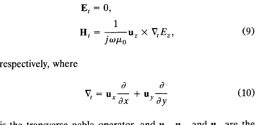
Figure 3 The transverse components of the electric and magnetic ields are
Related Figures (3)
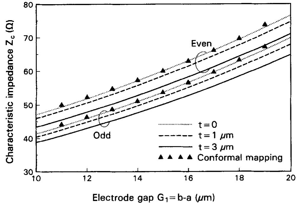
Figure 5 Calculated characteristic impedances as a function of electrode gap G, = b — a. The parameter is the electrode thickness ¢
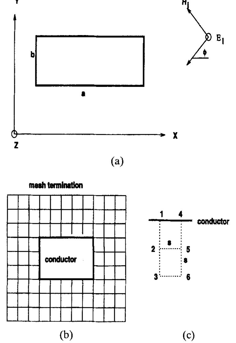
Figure 1 (a) Cross section of a rectangular cylindrical conductor, acting as a scatterer; (b) square mesh for the system of (a); (c) points used to evaluate magnetic field
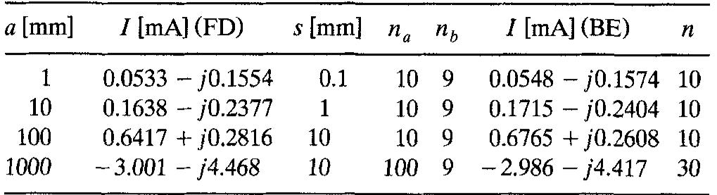
TABLE 1 Total current (/) on the cylinder of Figure 1, for a=b, 6 =0, E,;=1V/m, and f = 1 GHz, obtained by the finite-difference method (FD) and the boundary-element method (BE). Given also are the step size (s), the number of steps along a(n,), and the number of pulses per conductor side (n) for the boundary-element method. The phase of the electric field is zero at the conductor axis