index (original) (raw)
open
The Keyboard
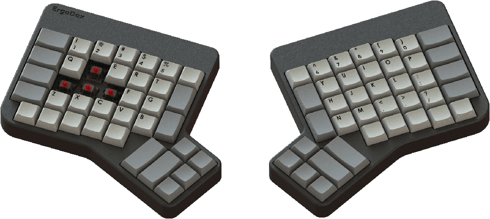
Ergodox is a keyboard project designed with ergonomics in mind, available either as a DIY kit or an assembled, commercial version. It uses 76-80 Cherry MX style mechanical switches (such as Cherry or Gateron) laid out in a columnar stagger (rather than the more conventional row stagger) layout with components that can easily be sourced. The keyboard is completely programmable and can be flashed with several different firmware options.
The entire project (including this website) is open source, allowing you the freedom to modify and tweak the project as you see fit.
Assembling this project will require some patience, soldering ability, and access to a computer to flash the firmware onto the keyboard.
Who built this?
The ErgoDox keyboard is a DIY keyboard project originally developed by “Dox” (Dominic Beauchamp) inspired by the Key64 Keyboard.
The printed circuit board was designed by “bpiphany” (Fredrik Atmer).
The original 3D printable case was designed by Dox but a far more popular and less expensive option was a layered acrylic design by litster.
The original firmware was designed by Ben Blazak.
The ErgoDox EZ was commercialized and manufactured by Erez Zukerman, Dmitry Slepov, and Yaara Lancet.
QMK Firmware which runs on the ErgoDox EZ was created by Jack Humbert, based on TMK.
This website was built by robotmaxtron with some help from the community as a way to centralize the documentation after ErgoDox.org went defunct. If you want to contribute to the project, pull requests, bugs (via Github issues) can be filed at our Github
Both the keyboard design and hardware files are licensed under the GNU Public License 3
Guide
A few things will need to be decided in advance before choosing parts or cases. The ErgoDox supports either the standard 76 key or 80 key layout.
This project will require some tools such as a soldering iron, flush cutters, wire strippers, solder, and possibly a screwdriver.
The build guide also assumes that you already know how to solder, if you do not know how to solder or want a refresher there are several guides available on YouTube and other places on the internet.
Parts Needed
To build an ErgoDox, some readily available components will need to be procured.
- Some notes on the electronics before purchasing:
- The Cherry MX style switches can be either pcb or plate mounted.
- Either through hole or surface mount diodes can be used as the pcb supports both including in-switch through hole diodes.
- If the typical 3mm red leds are not used, be sure to replace the 220 Ω resistors with ones that match the leds chosen.
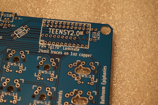
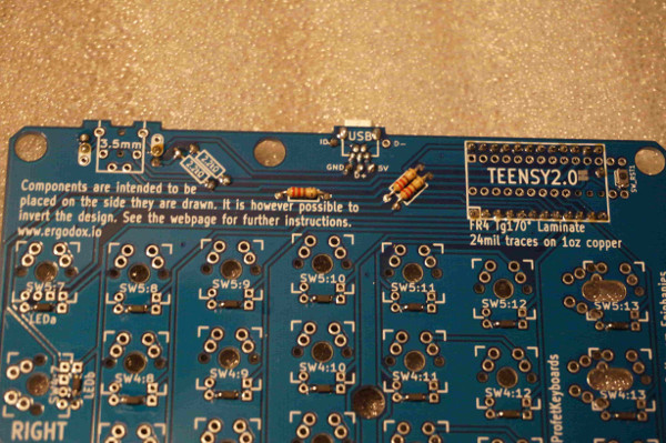
- PJRC sells a Teensy 2.0 both with and without header pins pre-installed. If you use a Teensy without the header pins pre-installed, you will need to obtain and install them.
- The pcb only supports currently three in switch LEDs on the inner colum of the right hand labeled LEDa, LEDb, and LEDc.
- Many if not all of the small components can be easily found online at vendors such as Mouser or Digikey.
Printed Circuit Boards
The pcb files are available in a separate repo available here should you wish to modify and/or produce them.
- The latest revision of the pcbs can be purchased from the following vendors
- Several vendors are available who generally stock some of the older revisions of the pcbs.
You could also buy the updated pcb from a vendor of choice by providing them the KiCad or Gerber files in the repo listed above or purchase a batch from OSH Park
Keep an eye out on the ErgoDox repo revision changelogs for updates and differences between pcb versions.
Small Electronics
- Full Parts list:
- 1x Pair of pcbs (one for each hand)
- 1x Teensy USB Board, Version 2.0
- 24x Teensy header pins, male (unless pre-installed)
- 1x MCP23018-E/SP I/O expander
- 76-80x Cherry MX switches, (depending on your layout)
- 76-80x 1N4148 diodes, SOD-123 package (Surface mount) or DO-35,(0.3” pitch) (through hole) (again, the amount needed will depend on your layout)
- 2x 2.2k Ω resistors (red, red, red)
- 3x 3mm T1 LEDs
- 3x 220 Ω resistors, or match to LED. (red, red, brown)
- 5x Short jumpers (You can also use the clipped off legs from your resistors)
- 1x 0.1 µF ceramic capacitor (marked “104” for 10*104 picofarad). Not strictly necessary but suggested
- 1x USB mini B connector WM17115
- 1x USB mini B plug with short cable (such as H2955)
- 1x USB cable male A to male mini B
- 2x 3.5 mm TRRS sockets, CP-43514. FC68129 will also work if its extra pins are snipped off
- 1x Cable with two 3.5 mm TRRS plugs
- 1x Ergodox Keyboard case
- 76-80x MX Keycaps
Case & Keycaps
While there are many options of materials available (such as cases carved out of wood) generally ErgoDox cases are either 3D printed or layered acrylic sheets.
The 3D printable case options are available in our repo and have been uploaded to Shapeways
The most popular and less expensive option is the layered acrylic design.Github Repo assembled with m3 bolts.
There is also a 3D printable tenting stand in the repo organization. This will prop up the ErgoDox using Litster’s case at a very natural and comfortable angle.
- Like any mechanical keyboard, keycaps will need to be obtained. In a normal 76 key configuration the following keycaps will be needed:
- 12x 1.5u
- 4x 2u
- 60x 1u
The 1.5u outer column keys can optionally be mounted closer in and 1u keycaps can be used.
Note: This layout is only supported on the newer (post 2012) revisions of the pcb and will require a modified plate design to support the new placement.
- If the 80 key layout is used, a slightly different keycap configuration will be needed replacing the 2u keys with two 1u keys each:
- 12x 1.5u
- 68x 1u
Assembly Guide
Now the section where the soldering and real assembly happens, in the next subsection there will be a couple external links to other build guides including both a photo and video build log.
- Arrange the pcbs face down and solder in the diodes to this side.
- Flip both of the pcbs over, this face up side (without the diodes) will be the side that the remaining components will be placed.
- Insert both the 2.2k ohm resistors and 220 ohm (or whatever resistors chosen appropriate for the leds selected) onto the right hand where labled on the pcb and solder into place.
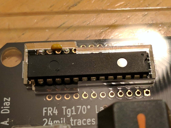
Note: Keep the legs clipped off the resistors, they can be used in a later step when the TRRS connections are installed. - On the left hand pcb, insert the I/O expander around the MCP23018 rectangle. The I/O expander is directional and the notch on the I/O expander should match up with the silkscreen. The notch on the expander will be facing ErgoDox printing on the circuit board. See the image in the next step for an example.
Note: There are three holes without copper pads and do not need to be soldered. - (Optional but suggested step) On the left hand pcb, insert the ceramic capacitor into the first and third holes of the top row and solder in place.
- 5a. Bridge with solder the two copper pads immediately to the left of the ceramic capacitor.
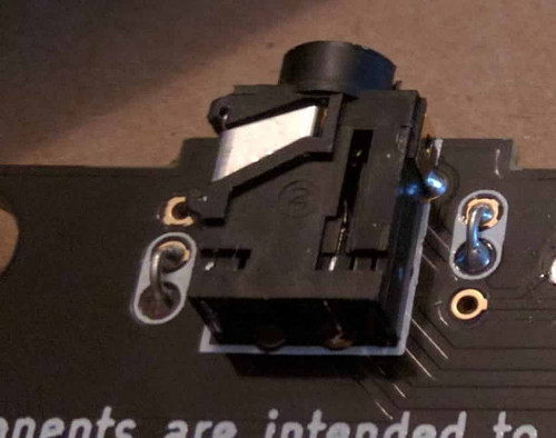
- Insert either jumper wire or the legs clipped from the resistors bent into a U, into both of the the white pairs of holes on either side of where the 3.5mm connections will go and solder in place.
- 6a. Place 3.5mm connection, solder the 4 connection points.
- 6b. Repeat both the jumper and 3.5mm connectors on the other hand.
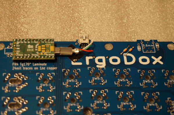
- Install the male jumper pins to the underside of the Teensy with the button face up and solder the pins to the top side of the Teensy.
Note: If the Teensy already has jumpers already installed, skip this step. - Insert the Teensy jumper legs from the Teensy assembly onto the right hand pcb with the usb facing the direction of the resistors and solder in place.
- Cut one of the mini usb cables about 1.5” from the connector.
- 9a. Strip off all of the sheathing from the cable, exposing the 4 wires.
- 9b. Place the following wires into their respective holes:
White: D- Red: 5v Green: D+ Black: GND- 9c. Solder wires to the pcb.
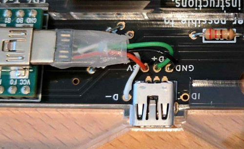
- On the right hand, insert the mini usb connector into the holes marked on the pcb and solder into place.
- Prepare the chosen case.
- 11a. If the layered acrylic case design is being used, peel off the protective film off the acrylic pieces.
* Place the pcb under the 3rd acrylic layer and insert the switches into the acylic plate making sure that both pins from the switch are extending out through the pcb. - 11b. If the 3D printed case is being used
* Place the pcb under the top section and push the switches into the case making sure that both pins from the switch are extending out through the pcb. - 11c. Solder switches in place.
Note: Make note of the location for the three switches on the right hand that will support the LEDs - On the right hand, insert the three leds through the housing of the three switches and solder into place.
Note: LEDs have polarity so be sure that the negative leg (which is the shorter of the two legs) of the LEDs goes into the (face up) square hole. - Finish assembling the case, plug in the TRRS cable between the two halves and proceed to building and flashing the selected firmware.
Other Assembly Guides
External links to some popular guides to building the ErgoDox Keyboard
More the video type? YouTube has several other good guides, this one I think does an excellent job of balancing information and length.
Imgur Build Log: user robotmaxtron shares his build log (including mistakes).
Firmware Guide
There are a number of options for the firmware powering the ErgoDox keyboard, each with their own sets of features and options. Please consult the README guides for each firmware for specific instructions on how to use and compile it.
QMK
A build guide for compiling and customizing your firmware is best found in the repo’s readme
Note: There are many users who have committed their keymaps that can be built on and easily adapted to suit your needs.
The ErgoDox-EZ Configurator tool can also be used to generate keymappings and their .hex files with QMK.
ErgoDox-EZ Configurator
This is a powerful graphical configurator that lets you define layers, dual-function keys, LED control, and more without having to code.
The configurator is based on QMK and outputs QMK source code which can be used as a starting point for your own configuration/editing.
TMK
The popular TMK firmware has also been ported to the ErgoDox.
Evan from TheVanKeyboards.com has built a TMK powered graphical configuration tool that supports the ErgoDox that can be used to create .hex files for flashing.
Original Ergodox Firmware
The originally designed firmware is also available, though somewhat fallen out of favor due to QMK and TMK’s improved functionalty and larger community support. The project has not had much movement since late 2015.
Online Massdrop Configurator
Massdrop has developed an online tool for generating ErgoDox keymaps without the need to compile your own firmware, suggested for users who might not be comfortable compiling their own firmware.
The underlying firmware behind the graphical tool is based on the original firmware by Ben Blazak.
Flashing your Ergodox
Once the firmware has been compiled down into a .hex file, it will need to be uploaded to the keyboard typically called flashing.
- Flashing your Ergodox is typically done with the Teensy Loader, and will be needed for the following guide.
- Locate your .hex file generated by your firmware of choice
- Start the Teensy Loader program
- Load the .hex file into it.
- Press the Reset button by pressing the reset button onboard the Teensy, you may need to insert something such as a paperclip or small screwdriver gently into the reset hole in the top right corner of your case.
Note: Some firmware (such as QMK and TMK) allow for the resetting of your atmel chip to be programmed as a keycode.- Click the button in the Teensy app to upload the firmware to your keyboard.
Variants
The open source nature of the ErgoDox has lead to several variants of the original design. The following list is not a comprehensive list, but does list many of the more popular designs.
Dactyl
Created by Matthew Adereth, the Dactyl Keyboard is a parameterized, split-hand, concave, columnar, ergonomic keyboard is an outstanding variation on the ErgoDox design.
Build Guide for the brave (will be improved over time)
The case is uploaded to the things directory of the Dactyl repo and has been uploaded to Shapeways
Clojure/conj Talk on 3D Printing Keyboards: Adereth gave a very interesting talk on the history of keyboards and the creation of the very interesting shape of the Dactyl Keyboard.
- Differences between the ErgoDox and the Dactyl:
- 70 key layout, removes the inner column of keys.
- 1u outer column keys rather than the standard 1.5u
- Handwired or flexible pcb
- Concave shaped switch mounting
- No official firmware but several options available.
ErgoDox EZ
Another fork of the ErgoDox is a pre-built version with a case that supports legs that will allow you to ‘tent’ or angle the ErgoDox-EZ.
- Firmware:
- QMK
- ErgoDox EZ Online Configurator for graphically configuring layouts (no coding required)
- TMK
- Differences between the original ErgoDox and the ErgoDox-EZ:
- Preassembled
- Custom-tooled case made from ABS plastic
- Two-year warranty
- Custom-built tilt/tent kit with metal legs that allow you to control the angle of the keyboard on your desk
- Custom-made wrist rest (wing) available
- Available with RGB LED case underglow
- As of January 2018, the ErgoDox-EZ now ships with hot swappable switches called CIY (Change It Yourself).
Infinity
Another variant of the ErgoDox is the ErgoDox Infinity developed by Input.club. This variant has added an LCD screen built into each half as well as a few other updates to the original design.
- Firmware options:
- Cases:
- Printed Circuit Board:
- Guides:
- Official Build Guide
- Reddit user keredomo has put together a set of Linux guides
1. The Infinity Ergodox: A Linux Guide
2. Modifying Firmware for Advanced Macros
3. Altering the Default LCD Screen
- Differences between the original ErgoDox and the Infinity:
- Full In-switch backlighting
- USB-C replaces TRRS between the two halves
- Each half can be used independently
- Pre-soldered smd components, only switches and LEDs will need to be soldered
- LCD screens on each keyboard half
- Proper costar stabilizer support
- ALPS switch support
Gamepad
User Profet23 of profetkeyboards.com has made some pcb updates that have been merged into the main pcb repo to allow for left hand only ErgoDox support. This is ideal as a gamepad or other single left-handed usage.
An example of the a finished build
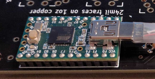
The PCB has now has pads that support the installation of an optional reset switch. The Teensy 2.0 is actually installed upside down, the built in reset switch is not accessible. There is also an extra hole for the Teensy to solder a header pin for the reset switch.
The new “top” of PCB. Teensy is installed upside down. 2.2k resistors, jumpers, and USB port installed on top. In this revision of the PCB, the jumpers dictate which side the USB port can be installed on as well as the TRRS port (which isn’t used in gamepad configuration).
Note: that the USB connection wires are installed (from left to right) empty, black, green, red, white. This is different from the silk screen layout as the usb port is now on "backwards".
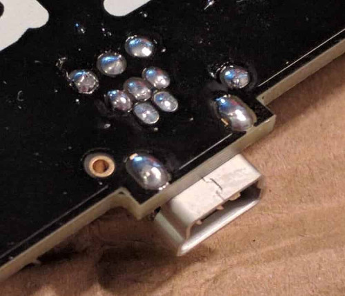
The new “bottom” of the PCB. The reset switch has been soldered to the bottom. LED resistors have also been soldered to bottom.