Arithmetic Logic Shift Unit (original) (raw)
Last Updated : 13 Oct, 2025
An Arithmetic Logic Shift Unit (ALSU) is an enhanced version of the Arithmetic Logic Unit (ALU) used in computer systems. It is a combinational digital circuit capable of performing arithmetic, logic, and shift micro-operations on binary data, and is a core part of the CPU datapath.
- Combines arithmetic, logical, and shift functionality in a single unit.
- Helps execute micro-operations efficiently during instruction cycles.
- Plays a crucial role in the register transfer mechanism.
**Basic Working of ALSU
Rather than having registers perform micro-operations independently, the system routes their data to a central ALSU via a common bus. The operation is completed in a single clock pulse, and the result is stored in a destination register.
- Data from source registers is fed to ALSU inputs.
- ALSU performs computation and returns output to the destination register.
- Operates in a single clock cycle in combinational designs.
**ALSU Functional Units
An ALSU integrates three primary sub-units: the arithmetic unit, the logic unit, and the shift unit. These sub-units work in parallel, and a multiplexer selects the final output based on control signals.
- Arithmetic Unit: Performs operations like ADD, SUB, INC, DEC.
- Logic Unit: Handles bitwise operations like AND, OR, XOR, NOT.
- Shift Unit: Executes SHL (Shift Left), SHR (Shift Right) operations.
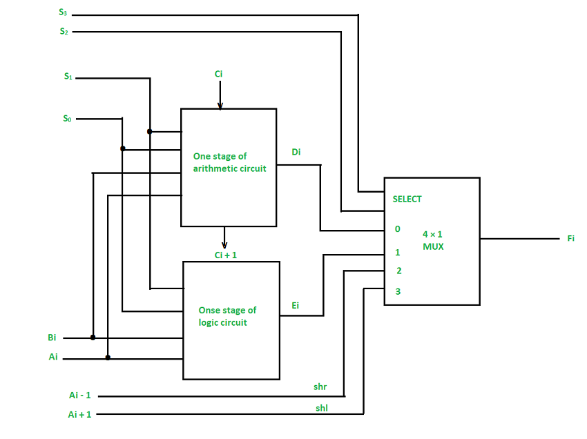
One stage of ALSU
**Control Signals and Operation Selection
Operations within the ALSU are selected using five control inputs: S3 S2 S1 S0 (4-bit opcode) and Cin (carry-in). The result from the arithmetic, logic, or shift unit is chosen via a 4×1 multiplexer based on these control signals.
- S3 S1 select the operation group: Arithmetic (00), Logic (01), Shift (10/11).
- S1 S0 select specific operations within each group.
- Cin is used in arithmetic operations to support carry/borrow.
**Shift Operation Handling in ALSU
Shift operations are treated as special cases within ALSU and utilize neighboring bit values for computation. For left shift (SHL), the value of the next lower bit is used; for right shift (SHR), the next higher bit is used.
- SHL input: Ai+1 is used as data source.
- SHR input: Ai-1 is used as data source.
- Output selection is done via the multiplexer at each stage.
**Operation Mapping in ALSU
The ALSU is designed to perform 14 distinct operations using the control signals S3 S2 S1 S0 and Cin. These are logically grouped into arithmetic, logic, and shift operations.
- Multiplexer selects the result based on control logic.
- Cin helps differentiate certain arithmetic operations.
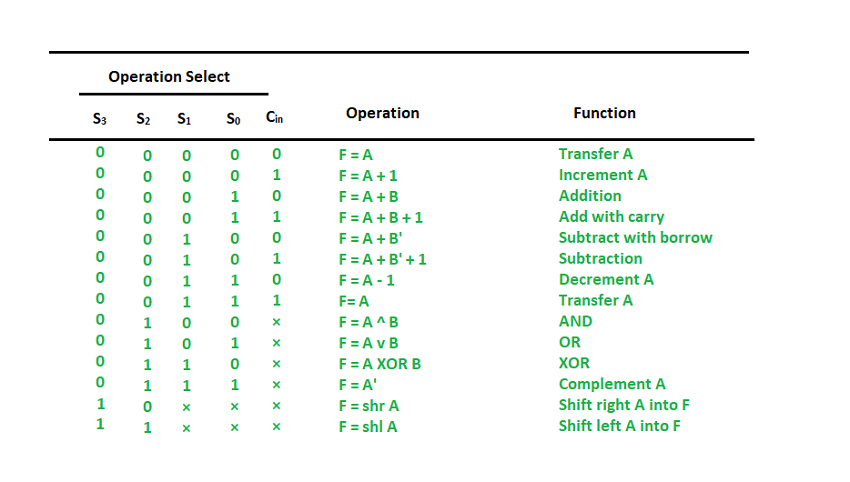
Function table of ALSU