Flag register in 8085 microprocessor (original) (raw)
Last Updated : 11 Jul, 2025
In the 8085 microprocessor, the Flag Register is a kind of 8-bit register comprising five flags that indicate the results from arithmetic and logical operations. These flags include the Sign flag, indicating whether the result is negative; the Zero flag, set in case the result is zero; the Auxiliary Carry flag used in BCD operations; the Parity flag, which indicates whether the result has an even number of 1s; and the Carry flag, set in case a carry or borrow occurs. In essence, these flags assist the microprocessor in decision-making based on the result of operations.
What is 8085 Microprocessor?
The general purpose means the 8085 microprocessor has to be relatively simple and inexpensive to implement many small to medium computation tasks. It follows the von Neumann architecture that uses one memory space for both instructions and data. It is capable of executing arithmetic, logical, and control operations and is designed to interact with external devices like memory, I/O ports, and other peripherals.
The **Flag register is a Special Purpose Register. Depending upon the value of the result after any arithmetic and logical operation, the flag bits become set (1) or reset (0). In 8085 microprocessor, the flag register consists of 8 bits and only 5 of them are useful. The 5 flags are:
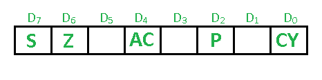
- **Sign Flag (S) - After any operation if the MSB (D(7)) of the result is 1, it indicates the number is negative and the sign flag becomes set, i.e. 1. If the MSB is 0, it indicates the number is positive and the sign flag becomes reset i.e. 0. from 00H to 7F, sign flag is 0 from 80H to FF, sign flag is 1 1- MSB is 1 (negative) 0- MSB is 0 (positive)
**Example: MVI A 30 (load 30H in register A) MVI B 40 (load 40H in register B) SUB B (A = A - B) These set of instructions will set the sign flag to 1 as 30 - 40 is a negative number. MVI A 40 (load 40H in register A) MVI B 30 (load 30H in register B) SUB B (A = A - B) These set of instructions will reset the sign flag to 0 as 40 - 30 is a positive number. - **Zero Flag (Z) - After any arithmetical or logical operation if the result is 0 (00)H, the zero flag becomes set i.e. 1, otherwise it becomes reset i.e. 0. 00H zero flags is 1. from 01H to FFH zero flag is 0 1- zero-result 0- non-zero result **Example: MVI A 10 (load 10H in register A) SUB A (A = A - A) These set of instructions will set the zero flag to 1 as 10H - 10H is 00H
- **Auxiliary Carry Flag (AC) - This flag is used in the BCD number system(0-9). If after any arithmetic or logical operation D(3) generates any carry and passes it on to D(4) this flag becomes set i.e. 1, otherwise, it becomes reset i.e. 0. This is the only flag register that is not accessible by the programmer 1-carry out from bit 3 on addition or borrows into bit 3 on subtraction 0-otherwise
**Example: MVI A 2BH (load 2BH in register A) MVI 39H (load 39H in register B) ADD B (A = A + B) These set of instructions will set the auxiliary carry flag to 1, as on adding 2B and 39, the addition of lower-order nibbles B and 9 will generate a carry. - **Parity Flag (P) - If after any arithmetic or logical operation the result has even parity, an even number of 1 bit, the parity register becomes set i.e. 1, otherwise it becomes reset i.e. 0. 1-accumulator has an even number of 1 bits 0-accumulator has odd parity
**Example: MVI A 05 (load 05H in register A) This instruction will set the parity flag to 1 as the BCD code of 05H is 00000101, which contains an even number of ones i.e. 2. - **Carry Flag (CY) - Carry is generated when performing n bit operations and the result is more than n bits, then this flag becomes set i.e. 1, otherwise, it becomes reset i.e. 0. During subtraction (A-B), if A>B it becomes reset, and if (A<B) it becomes set. Carry flag is also called the borrow flag. 1-carry out from MSB bit on addition or borrow into MSB bit on subtraction 0-no carry out or borrow into MSB bit.
**Example: MVI A 30 (load 30H in register A) MVI B 40 (load 40H in register B) SUB B (A = A - B) These set of instructions will set the carry flag to 1 as 30 - 40 generates a carry/borrow. MVI A 40 (load 40H in register A) MVI B 30 (load 30H in register B) SUB B (A = A - B) These set of instructions will reset the carry flag to 0 as 40 - 30 does not generate any carry/borrow.
What is Flag Register ?
The Flag register is a 8-bit register in the 8085 microprocessor that contains information about the status of the arithmetic and logic operations performed by the processor. The bits in the Flag register are used to indicate whether the result of an operation is zero, positive, negative, or if there was a carry or borrow during the operation.
The Flag register is used by the processor to make decisions based on the results of arithmetic and logic operations, such as branching to a different instruction based on the value of a flag.
Uses of Flag Register
- Conditional branching: The flags in the Flag register are used to make decisions about whether to branch to a different instruction or not. For example, the Jump on Zero (JZ) instruction checks the Zero Flag to see if the result of the previous operation was zero. If it was, the program counter is changed to jump to a different address.
- Arithmetic operations: The Flag register is used extensively during arithmetic operations such as addition, subtraction, multiplication, and division. The Carry Flag is used to detect if there was a carry during addition or a borrow during subtraction. The Auxiliary Carry Flag is used to detect if there was a carry from the 3rd bit to the 4th bit during addition or a borrow from the 4th bit to the 3rd bit during subtraction.
- Logical operations: The Flag register is also used during logical operations such as AND, OR, and XOR. The Zero Flag is used to detect if the result of the logical operation was zero. The Sign Flag is used to detect if the result was negative.
- System calls: The Flag register is used by the operating system to determine the status of the CPU before and after a system call. For example, the operating system might check the Carry Flag to see if there was a carry during an arithmetic operation, and then take appropriate action based on the result.
Advantages
- **Efficient error detection: The flag register can be used to efficiently detect errors and other conditions during program execution. For example, the carry flag can be used to detect overflow or underflow during arithmetic operations.
- **Simplifies branching: The flags can be used to make decisions about branching and other control flow operations. For example, the zero flag can be used to determine if a value is zero, and the sign flag can be used to determine if a value is negative.
- **Saves memory: The flag register can help reduce the amount of memory required for storing status information.
- **Faster execution: By using flags instead of performing additional operations to check conditions, the 8085 microprocessor can execute programs more quickly.
Disadvantages
- **Limited information: The flag register provides a limited set of status information that may not be sufficient for all applications.
- **Limited control: The flags in the flag register are set or cleared automatically by the processor and cannot be directly manipulated by the programmer.
- **Complexity: The use of flags can add complexity to programming and debugging, particularly when multiple flags are used in conjunction with one another.
- **Overwriting: Since the flag register is also used for other purposes, such as storing the stack pointer, the status flags can be accidentally overwritten during program execution.
Applications of 8085 Microprocessor
A few of the applications of the microprocessor 8085 involve the following:
- **Embedded Systems: Many embedded systems used 8085 for applications such as control system, instrumentation, and communications.
- **Education: The 8085 has widely found applications as teaching in courses of microprocessors due to its simple architecture.
- **Traffic Light Control Systems: It finds application in simple automation tasks, for example, controlling the lights of traffic or another sort of sequencing applications.
- **Home Appliances: From washer and dryer to microwave oven, this small appliance of microprocessor found its home. Industrial Automation: It played a major role in controlling machinery and automation systems of industries during its time.
Conclusion
This Flag in the 8085 microprocessor plays a vital role in handling signed arithmetic operations by signaling overflows. This helps in maintaining the integrity of calculations, showing when the result of an operation exceeds the range that can be represented with signed numbers. An effective understanding of the role of the V-Flag will, therefore, be quite helpful in programming and debugging systems undertaken with the 8085 microprocessor.