Interface 8254 PIT with 8085 microprocessor (original) (raw)
Last Updated : 21 Apr, 2026
8254 PIT is an IC interfaced with 8085 to generate accurate timing signals. It has three 16-bit counters operating in different modes.
To interface the 8254 PIT with the 8085 microprocessor, you need to connect the appropriate address and data lines between the two devices. You also need to set the appropriate control signals to configure the 8254 PIT for the desired timing operation.
Here are the steps to interface the 8254 PIT with the 8085 microprocessor:
- Connect the address and data lines between the 8254 PIT and the 8085 microprocessor.
- Set the mode of operation using the control register.
- Load the initial count value into the counter. This sets the initial value for the counter and determines the period of the output signal.
- Enable the counter by setting the appropriate control signals. This allows the counter to start counting and generates the output signal.
- Monitor the output signal of the 8254 PIT. The output signal can be used as a timing reference signal for other parts of the system.
Prerequisite - 8254 Control Register and Operating modes
**Problem: Write an assembly language program in 8085 microprocessor which generates 1 KHz square waveform by using counter 1 as a binary counter if clock frequency of 8254 is 2 MHz.
**Assumption: Assume the port addresses are 80H, 81H, 82H, 83H for C0(Counter 0), C1(Counter 1), C2(Counter 2), CR(Control Register).
For the above problem, 8254 works in Mode 3 (square wave generator).
Count for register = clock frequency / square wave frequency
= 2 MHz / 1 KHz = 2000 = (07D0)H
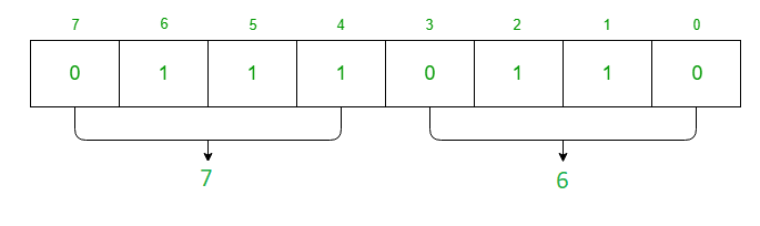
- Now the data is 16-bit, so RW1 = 1 and RW0 = 1 in Control Register.
- To select C1 (Counter 1) → SC1 = 0 and SC0 = 1.
- For Mode 3 → M2 = 1, M1 = 1, M0 = 1.
- For binary counter → LSB (BCD) = 0.
Hence the Control Register (CR) is: 01110110 = 76H
 **Algorithm
- Move the data 76 in A
- Display the contents of A to port 83
- Move the data D0 in A
- Display the contents of A to port 81
- Move the data 07 in A
- Display the contents of A to port 81
- Stop
**Program
| MEMORY ADDRESS | MNEMONICS | COMMENT |
|---|---|---|
| 2000 | MVI A 76 | A <- 76 |
| 2002 | OUT 83 | CR <- A |
| 2004 | MVI A D0 | A <- D0 |
| 2006 | OUT 81 | C1 <- A |
| 2008 | MVI A 07 | A <- 07 |
| 200A | OUT 81 | C1 <- A |
| 200C | HLT | Stop |
**Explanation
- **MVI A 76 is used to move the content of CR(Control Register) to register A.
- **OUT 83 is used to assign the value of A to port 83 which is Control Register.
- **MVI A D0 is used to move the lower byte of data of Counter 1 to register A.
- **OUT 81 is used to assign the value of A to port 81 which is Counter 1.
- **MVI A 07 is used to move the higher byte of data of Counter 1 to register A.
- **OUT 81 is used to assign the value of A to port 81 which is Counter 1.
- **HLT is used end the program.
**Uses of 8254 PIT with 8085 microprocessor
- Interrupt generation: The 8254 PIT can be programmed to generate an interrupt signal after a specific time interval. This can be useful in applications that require periodic tasks to be performed, such as data acquisition, data logging, and control systems.
- Pulse width modulation (PWM): The 8254 PIT can be used to generate a PWM signal, which is a widely used technique for controlling the power delivered to a load. PWM signals are used in applications such as motor speed control, lighting control, and audio amplifiers.
- Real-time clock: The 8254 PIT can be used to implement a real-time clock that can keep track of the time and date. This is useful in applications such as alarm clocks, digital watches, and embedded systems that require accurate timekeeping.
- Frequency generation: The 8254 PIT can be used to generate a signal with a specific frequency. This can be useful in applications such as signal generators, tone generators, and test equipment.
- Pulse generation: The 8254 PIT can be used to generate a pulse with a specific width and period. This can be useful in applications such as timing circuits, delay circuits, and pulse-width modulators.
- Digital signal processing: The 8254 PIT can be used as a clock source for digital signal processing circuits. This is useful in applications such as digital filters, Fourier transforms, and signal generators.
- Synchronization: The 8254 PIT can be used to synchronize the timing of multiple devices. This is useful in applications such as data communication, video processing, and audio processing.
**Issues in 8254 PIT with 8085 microprocessor
- Timing accuracy: The accuracy of the timing signals generated by the 8254 PIT may be affected by factors such as temperature, voltage fluctuations, and component aging. As a result, the accuracy of the timing signals may degrade over time, leading to errors in the system.
- Interrupt conflicts: When using the 8254 PIT to generate interrupts, there may be conflicts with other devices that also generate interrupts. This can result in missed interrupts, which may affect the overall performance of the system.
- Signal noise: The 8254 PIT may be susceptible to signal noise, which can cause glitches in the timing signals generated by the device. This can lead to errors in the system and may require additional filtering or noise reduction techniques.
- Hardware limitations: The 8254 PIT has a limited number of input and output ports, which may limit the number of devices that can be connected to the system. Additionally, the 8085 microprocessor has a limited number of address and data lines, which may restrict the amount of memory and I/O devices that can be connected to the system.
- Programming complexity: The 8254 PIT requires programming to configure its timing parameters and operating modes. This programming can be complex, and errors in the programming may lead to incorrect timing signals or other issues in the system.
Features
- **Pin compatibility: The 8254 PIT is typically pin-compatible with the 8085 microprocessor, which means that it can be connected to the microprocessor using the same address, data, and control lines.
- **Memory-mapped I/O: The 8254 PIT is typically accessed through memory-mapped I/O, which means that it is treated as a memory location and accessed using the same instructions as memory access. The microprocessor sends a specific address to the 8254 PIT, which activates the appropriate control signals to read from or write to the timer.
- **Three channels: The 8254 PIT has three independent timer channels, each of which can be programmed to operate in a different mode. Each channel has a 16-bit counter that can be programmed to count up or down, and the output of the timer can be used to trigger an interrupt or to control other devices.
- **Modes of operation: The 8254 PIT can operate in a variety of modes, including the interval timer mode, the rate generator mode, and the square wave mode. In interval timer mode, the timer generates an interrupt after a specified time interval has elapsed. In rate generator mode, the timer generates a periodic signal with a specified frequency. In square wave mode, the timer generates a square wave with a specified duty cycle.
- **Cascading: The 8254 PIT can be cascaded to allow for longer time delays or higher frequencies. This involves connecting the output of one timer to the input of another timer, which effectively increases the number of bits in the counter and extends the range of the timer.
Advantages
- **Flexibility: The 8254 PIT is a highly flexible peripheral device that can generate a wide range of timing and control signals. This makes it suitable for a variety of applications in a computer system.
- **Accurate Timing: The 8254 PIT has the capability to generate highly accurate timing signals, which is essential for many computer applications such as real-time systems.
- **Improved System Performance: By offloading the generation of timing and control signals to the 8254 PIT, the 8085 microprocessor can focus on executing application programs, thereby improving system performance.
- **Easy to Interface: The 8254 PIT can be easily interfaced with an 8085 microprocessor using standard I/O instructions.
Disadvantages
- **Increased Complexity: Interfacing the 8254 PIT with an 8085 microprocessor requires additional hardware and software, which can increase the complexity of the system.
- **Additional Cost: The 8254 PIT is an additional peripheral device that must be purchased and installed, which can increase the cost of the system.
- **Limited Compatibility: The 8254 PIT may not be compatible with all types of microprocessors, which can limit the flexibility of the system.
- **Additional Maintenance: The 8254 PIT requires additional maintenance and support as it is a separate component from the 8085 microprocessor. This can increase the cost and complexity of the system.