3 bit Synchronous Down Counter (original) (raw)
Last Updated : 23 Jul, 2025
Prerequisite : Counter , Synchronous counter.
3 bit Synchronous Down Counter :
- In synchronous counter clock is provided to all the flip-flops simultaneously.
- Circuit becomes complex as the number of states increases.
- Speed is high.
Design : The steps involves in design are
1. Decide the number of Flip flops -
N number of Flip flop(FF) required for N bit counter.
- For 3 bit counter we require 3 FF.
- Maximum count = 2n-1, where n is a number of bits.
- For n= 3, Maximum count = 7.
- Here T FF is used.
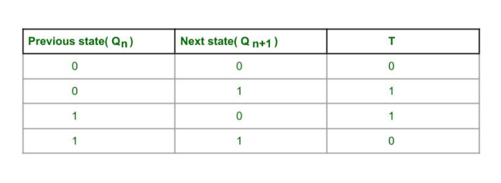
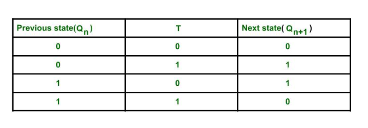
2. Write excitation table of FF -
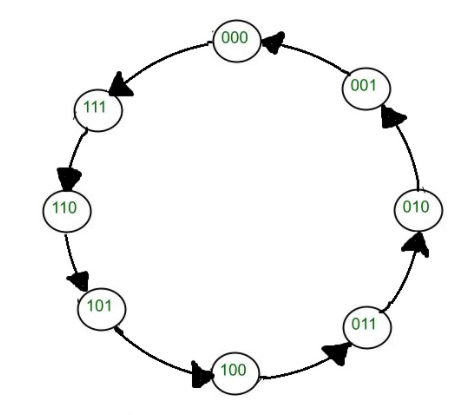
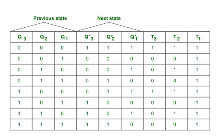
3. Draw State diagram and circuit excitation table -
Number of states = 2n, where n is number of bits.
Here T = 1, then there is output state(next state changes from previous state) changes i.e Q changes from 0 to 1 or 1 to 0
T= 0 then, there is no state output state changes i.e Q remains same
4. Find simplified equation using k map -
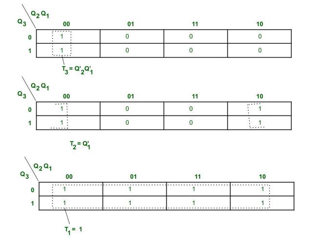
K map for 3 bit synchronous down counter
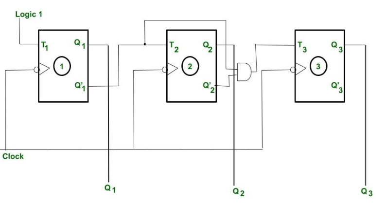
5. Create circuit diagram -
The clock is provided to every Flip flop at same instant of time.
The toggle(T) input is provided to every Flip flop according to the simplified equation of K map.
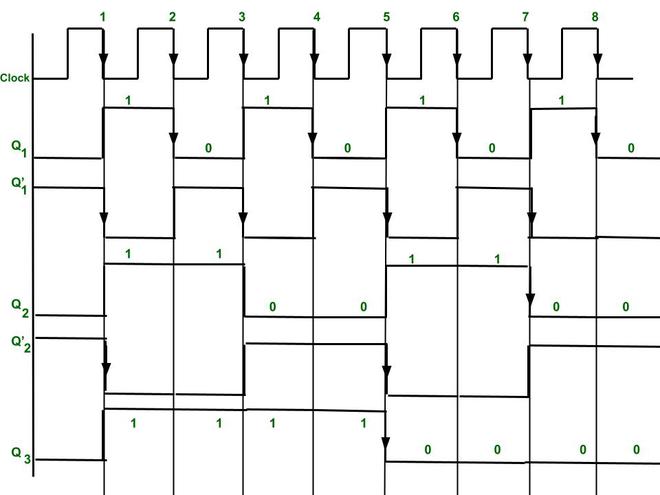
Timing diagram of 3 bit synchronous Down counter.
Explanation :
Here -ve edge triggered clock is used for toggling purpose.
As we see from characteristics table when T = 1, then toggling takes place and T =0 then it stores the output state.
- Initially Q3 = 0, Q2= 0, Q1= 0.
- In simplified equation of K map we get T1 = 1, therefore Flip flop 1 output Q1 is toggle for every negative edge(because clock is negative edge triggered). Flip-flop(FF) 2 toggle input(T2) is connected to Q'1. Therefore, Flip Flop 2 output state Q2 is toggle only when there is clock falling edge (i.e -ve edge triggering) and Q'1 =1.
- Similarly, Flip flop 3 toggle input(T) is connected to Q'2 and Q'1. Therefore, Flip flop 3 output is toggle when there is clock falling edge and Q'2=1 and Q'1 = 1 .(as you can see from timing diagram)
- Therefore, we get output(as down counting Q3(MSB) Q2 Q1(LSB) after 8th -ve edge triggered clock the output of the three Flip flops again becomes Q3 = 0, Q2 = 0, Q1 =0.
- We get output(state changes) after every -ve edge clock pulse.
- By 3 Flip flop we get output as 23-1= 7 to 0.