Combinational circuits using Decoder (original) (raw)
Last Updated : 26 Nov, 2025
Combinational circuits utilizing decoders are basic parts in a computerized plan, assuming a significant part in making an interpretation of parallel data into noteworthy results. Decoders are combinational rationale gadgets that convert twofold information signals into an extraordinary arrangement of results, each addressing a particular blend of information values. They are instrumental in different applications, for example, memory address unraveling, information directing, and show frameworks. By utilizing decoders, planners can make productive and flexible circuits that work with complex rationale activities and improve framework usefulness. Understanding the coordination of decoders into combinational circuits is fundamental for streamlining computerized frameworks and accomplishing dependable execution.
What is Combinational Circuit?
A combinational circuit is a kind of computerized circuit where the result is exclusively reliant upon the ongoing contributions, with no memory or input components included. This implies that the result is an immediate consequence of the info values out of the blue, reflecting quick changes immediately. Combinational circuits perform different legitimate tasks like expansion, deduction, and information-directing through parts like rationale doors, multiplexers, and decoders. They are major in advanced frameworks for making useful units like number-crunching rationale units (ALUs) and information selectors, offering unsurprising and direct conduct in view of their feedback conditions.
What is Decoder?
A Decoder is a computerized circuit that changes over twofold data from a n-bit contribution to a one-of-2^n result, where just a single result line is enacted at a time. It basically makes an interpretation of double code into a particular arrangement of results, empowering the determination of a solitary result line in view of the twofold information value. Decoders are broadly utilized in different applications, for example, memory address deciphering, information directing, and show frameworks (e.g., seven-portion shows). For instance, a 3-to-8 decoder has 3 info lines and 8 result lines, where every mix of the 3 info bits compares to one dynamic result line.
**Decoder as a De-Multiplexer
A Decoder with Enable input can function as a demultiplexer. A demultiplexer is a circuit that receives information from a single line and directs it to one of
2^n
possible output lines.
A
2^n
demultiplexer receives as input,
n
selection lines and one Input line. These selection lines are used to select one output line out of
2^n
possible lines. To implement a
2^n
demultiplexer, we use a
n:2^n
decoder with Enable input. The
n
selection lines of the demultiplexer are the
n
input lines that the decoder gets and the one input line of demultiplexer is the Enable input of the Decoder.
Making 1:4 demultiplexer using 2:4 Decoder with Enable input. Let A, B be the selection lines and EN be the input line for the demultiplexer.
The decoder shown below functions as a 2:4 demultiplexer when EN is taken as a data input line and A and B are taken as the selection inputs. The single input variable E has a path to all four outputs, but the input information is directed to only one of the output lines, as specified by the binary combination of the two selection lines A and B. This can be verified from the truth table of the circuit.
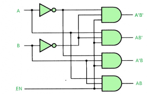
**Truth Table-
\begin{tabular}{|c|c|c||c|c|c|c|} \hline E & A & B & D_0 & D_1 & D_2 & D_3\\ \hline \hline 0 & X & X & 0 & 0 & 0 & 0\\ \hline 1 & 0 & 0 & 1 & 0 & 0 & 0\\ \hline 1 & 0 & 1 & 0 & 1 & 0 & 0\\ \hline 1 & 1 & 0 & 0 & 0 & 1 & 0\\ \hline 1 & 1 & 1 & 0 & 0 & 0 & 1\\ \hline \end{tabular}
**Combinational Logic Implementation using Decoder
A decoder takes
n
input lines and has
2^n
output lines. These output lines can provide the
2^n
minterms of
n
input variables.
Since any Boolean function can be expressed as a sum of minterms, a decoder that can generate these minterms along with external OR gates that form their logical sums, can be used to form a circuit of any boolean function.
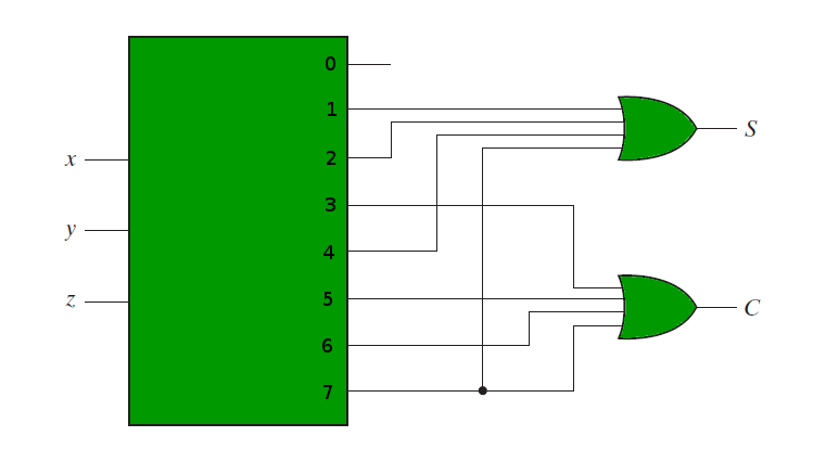
For example, if we need to implement the logic of a full adder, we need a 3:8 decoder and OR gates. The input to the full adder, first and second bits and carry bit, are used as input to the decoder. Let x, y and z represent these three bits. Sum and Carry outputs of a full adder have the following truth tables-
\begin{tabular}{|c|c|c||c|c|} \hline x & y & z & S & C\\ \hline \hline 0 & 0 & 0 & 0 & 0\\ \hline 0 & 0 & 1 & 1 & 0\\ \hline 0 & 1 & 0 & 1 & 0\\ \hline 0 & 1 & 1 & 0 & 1\\ \hline 1 & 0 & 0 & 1 & 0\\ \hline 1 & 0 & 1 & 0 & 1\\ \hline 1 & 1 & 0 & 0 & 1\\ \hline 1 & 1 & 1 & 1 & 1\\ \hline \end{tabular}
Therefore we have-
S = \sum (1, 2, 4, 7)
C = \sum (3, 5, 6, 7)
The following circuit diagram shows the implementation of Full adder using a 3:8 Decoder and OR gates.
**Advantages of Combinational circuits using Decoder
- **1.Simplification: Combinational circuits utilizing Decoder can improve on the plan of complicated advanced circuits by diminishing the quantity of information sources required and the intricacy of the rationale capabilities.
- **2.Flexibility: Combinational circuits utilizing Decoder can be utilized in a large number of utilizations since they can change over paired codes into one-hot codes that can be utilized to control other circuit parts like multiplexers, demultiplexers, or memory gadgets.
- **3.Modularity: Combinational circuits utilizing Decoder can be effectively scaled and coordinated into bigger computerized frameworks since they are secluded and can be flowed to make more perplexing circuits.
- **4.Reliability: Combinational circuits utilizing Decoder are dependable and have a low likelihood of failing since they are made out of straightforward, surely knew parts.
**Disadvantages of Combinational circuits using Decoder
- **1.Complexity: Combinational circuits utilizing Decoder can be complicated and require cautious plan to guarantee that the rationale capabilities are accurately executed and that there are no race conditions or errors.
- **2.Delay: Combinational circuits utilizing Decoder can bring delay into the circuit since the Decoder expects time to change over the information code into the one-hot result code.
- **3.Power utilization: Combinational circuits utilizing Decoder can consume more power than different sorts of circuits since they require various parts to carry out the rationale capabilities.
- **4.Limited adaptability: Combinational circuits utilizing Decoder are restricted to changing over parallel codes into one-hot codes, which can be a detriment in applications that require more mind boggling rationale works or backing for different kinds of codes.
Application of Combinational circuits using Decoder
- **Memory Address Disentangling: Decoders are utilized to choose explicit memory areas in Slam or ROM by unraveling the location lines and empowering the suitable memory chip or addressable area.
- **Information Steering: In information correspondence frameworks, decoders direct information to the right objective or handling unit in view of the decoded address or order signals.
- **Show Frameworks: Decoders drive shows, for example, seven-fragment shows, by changing over twofold info values into signals that initiate the right portions to address digits or characters.
- **Guidance Disentangling: In microchips, decoders decipher machine guidelines and produce control signals for executing explicit tasks.
- **Advanced Switches: Decoders control the exchanging of various gadgets or lines in view of twofold information, considering complex control plans in electronic frameworks.