Encoders (original) (raw)
Last Updated : 20 Feb, 2026
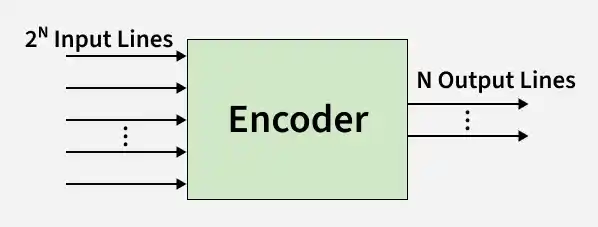
An encoder is a digital combinational circuit that converts multiple input signals into a binary code. It typically has one active input at a time and generates a binary output representing the position of that active input.
- The number of inputs is usually 2n, with n output lines.
- Inputs are usually active high, meaning high voltage represents an active signal.
- Binary-weighted encoders assign codes based on input position using binary values.
- Encoders help convert parallel inputs into compact binary formats for processing.
- Encoders are useful in digital systems for data compression and efficient transmission.
- For example, a 4-to-2 encoder has four inputs and produces a 2-bit output code.
Encoder
Types of Encoders
1. 4 to 2 Encoder
The 4 to 2 Encoder consists of four inputs Y3, Y2, Y1 & Y0, and two outputs A1 & A0. At any time, only one of these 4 inputs can be ‘1’ in order to get the respective binary code at the output. The figure below shows the logic symbol of the 4 to 2 encoder.
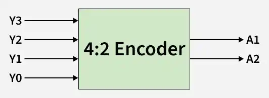
4 to 2 Encoder
**Truth Table
The Truth table of 4 to 2 encoders is as follows:
| INPUTS(Y3Y2Y1Y0) | OUTPUTS(A1A0) |
|---|---|
| 0001 | 00 |
| 0010 | 01 |
| 0100 | 10 |
| 1000 | 11 |
Logical expression for A1 and A0:
A1 = Y3 + Y2
A0 = Y3 + Y1
**Circuit Diagram
The above two Boolean functions A1 and A0 can be implemented using two input OR gates:
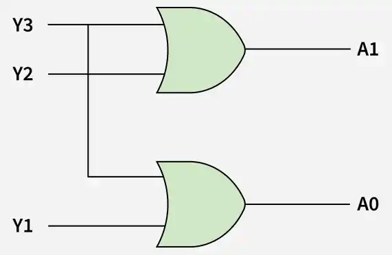
Implementation using OR Gate
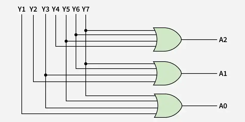
2. Octal to Binary Encoder (8 to 3 Encoder)
The 8 to 3 Encoder or octal to Binary encoder consists of 8 inputs: Y7 to Y0 and 3 outputs: A2, A1 & A0. Each input line corresponds to each octal digit value and three outputs generate corresponding binary code. The figure below shows the logic symbol of octal to the binary encoder.
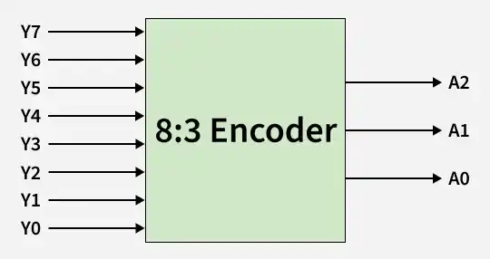
Octal to Binary Encoder (8 to 3 Encoder)
**Truth Table
| INPUTS(Y7Y6Y5Y4Y3Y2Y1Y0) | OUTPUTS(A2A1A0) |
|---|---|
| 00000001 | 000 |
| 00000010 | 001 |
| 00000100 | 010 |
| 00001000 | 011 |
| 00010000 | 100 |
| 00100000 | 101 |
| 01000000 | 110 |
| 10000000 | 111 |
Logical expression for A2, A1, and A0:
A2 = Y7 + Y6 + Y5 + Y4
A1 = Y7 + Y6 + Y3 + Y2
A0 = Y7 + Y5 + Y3 + Y1
**Circuit Diagram
The above three Boolean functions A2, A1, and A0 can be implemented using four input OR gates:
Implementation using OR Gate
3. Decimal to BCD Encoder
The decimal-to-binary encoder usually consists of 10 input lines and 4 output lines. Each input line corresponds to each decimal digit and 4 outputs correspond to the BCD code. This encoder accepts the decoded decimal data as an input and encodes it to the BCD output which is available on the output lines. The figure below shows the logic symbol of the decimal to BCD encoder.
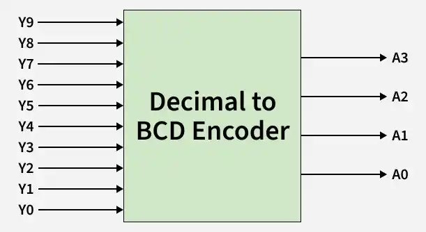
Decimal to BCD Encoder
**Truth Table
| INPUTS(Y9Y8Y7Y6Y5Y4Y3Y2Y1Y0) | OUTPUTS(A3A2A1A0) |
|---|---|
| 0000000001 | 0000 |
| 0000000010 | 0001 |
| 0000000100 | 0010 |
| 0000001000 | 0011 |
| 0000010000 | 0100 |
| 0000100000 | 0101 |
| 0001000000 | 0110 |
| 0010000000 | 0111 |
| 0100000000 | 1000 |
| 1000000000 | 1001 |
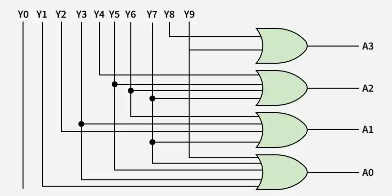
Logical expression for A3, A2, A1, and A0:
A3 = Y9 + Y8
A2 = Y7 + Y6 + Y5 +Y4
A1 = Y7 + Y6 + Y3 +Y2
A0 = Y9 + Y7 +Y5 +Y3 + Y1
**Circuit Diagram
The above two Boolean functions can be implemented using OR gates:
Implementation using OR Gate
4. Priority Encoder
A 4 to 2 priority encoder has 4 inputs: Y3, Y2, Y1 & Y0, and 2 outputs: A1 & A0. Here, the input, Y3 has the highest priority, whereas the input, Y0 has the lowest priority. In this case, even if more than one input is ‘1’ at the same time, the output will be the (binary) code corresponding to the input, which is having higher priority.
**Truth Table
| INPUTS(Y3Y2Y1Y0) | OUTPUTS(A1A0V) |
|---|---|
| 0000 | XX0 |
| 0001 | 001 |
| 001X | 011 |
| 01XX | 101 |
| 1XXX | 111 |
**Logical Expressions using K-Map
The logical expression for A1 is shown below:
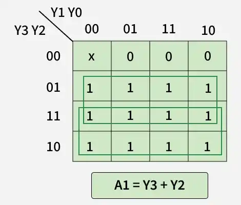
Logical Expression
The Logical Expression for A0 is shown below:
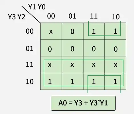
Logical Expression
**Circuit Diagram
The above two Boolean functions can be implemented as:
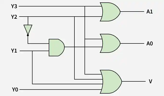
Priority Encoder
Errors in Encoders
There is an ambiguity, when all outputs of the encoder are equal to zero.
- If more than one input is active High, then the encoder produces an output, which may not be the correct code.
- In a simple encoder, when all inputs are LOW, the output is 0. This creates confusion because the output 0 may also represent a valid input (for example, input line 0 active).
- Basic encoders cannot determine which input to encode if multiple inputs are HIGH at the same time, leading to unpredictable or incorrect outputs.
So, to overcome these difficulties, we should assign priorities to each input of the encoder. Then, the output of the encoder will be the code corresponding to the active high inputs, which have higher priority.