Operational Amplifier (opamp) in Digital Electronics (original) (raw)
Last Updated : 26 Nov, 2025
An amplifier is a device that increases the strength of the input signal. It can be Voltage amplifiers, whose input is some voltage and output is also a voltage but amplified. Current amplifier, whose input is some current and output is also a current but amplified.
- **Transconductance Amplifier: Whose input is some voltage and output is the current.
- **Transimpedance Amplifier: Whose input is some current and output is the voltage.
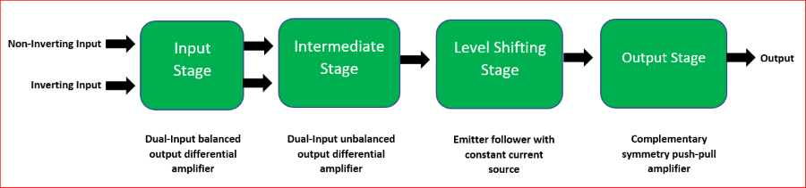
Block diagram of an op-amp
An operational amplifier (or, op-amp) is a voltage amplification, three-terminal electronic device, having two input terminals namely Inverting terminal (marked by '-' sign in diagrams) and a Non-inverting terminal(marked by '+' sign in diagrams), and the third terminal is the output terminal. Gain ("A") of the op-amp = output signal/input signal
Different Configurations of Operational Amplifier:
**Open Loop Configuration
In this configuration, the op-amp does not have any feedback. Ideally, it has an infinite open-loop gain(practically hundreds of thousands of times larger than the potential difference between its input terminals).
**Inverting Mode:
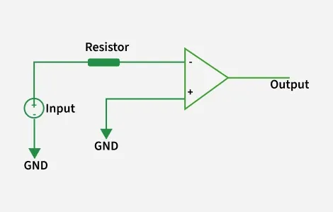
Inverting closed loop op-amp
**Non-inverting Mode:
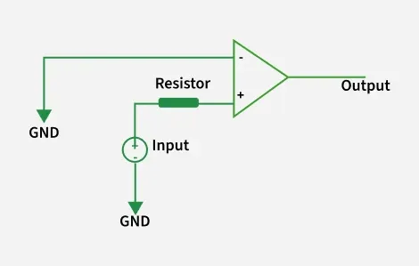
Non-inverting open loop op-amp
**Closed Loop Configuration
In this configuration of the op-amp, negative feedback is used i.e., a portion of the output voltage is applied back to the **inverting input. This feedback greatly reduces the gain of the op-amp as compared to open-loop gain. Thus, it is a kind of controlled way of amplification.
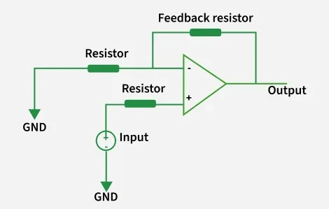
**Inverting Mode:
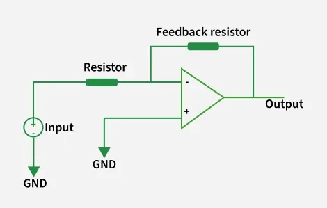
Inverting closed loop op-amp
**Non-inverting Mode:
Non-inverting closed loop op-amp
**Characteristic of an ideal Operational Amplifier:
- **Open Loop gain: Ideally op-amp should have an infinite open-loop gain (practically it is hundreds of thousands of times larger than the potential difference between its input terminals).
- **Input impedance or resistance: Ideally op-amp should have infinite input resistance (practically it should be very high).
- **Output impedance or resistance: Ideally op-amp should have zero output resistance (practically it should be very low).
- **Bandwidth: Ideally op-amp should have infinite bandwidth (practically it is limited).
- **CMRR: Ideally op-amp should have infinite CMRR, Common Mode Rejection Ratio so that common noise voltage in the output becomes zero.
- **Slew Rate: Ideally op-amp should have infinite SR, slew rate so that any change in the input voltage simultaneously changes the output voltage.
**Basic Terminologies of an Operational Amplifier:
**1. Slew Rate: The Slew rate (SR) of an op-amp is defined as the maximum rate of change of output voltage per unit of time. It is represented as volts per microsecond ( V/_μs).
SR = (**dVo / **dt) |max
**2. Output Offset Voltage: Output of the op-amp should be ideally zero when the voltage difference between the inputs is zero but, practically the output is non-zero, there is a voltage of very small magnitude. This unwanted voltage at the output side when no input is given is called Output Offset Voltage.
**3. Input Offset Current: Magnitude of the difference of current entering inverting and non-inverting terminals, when no input voltage is given to op-amp.
Io = |Ib1-Ib2|; Io-Input Offset Current, Ib1 & Ib2-current at input terminals
**4. Input Bias Current:
I(bias) = (Ib1+Ib2)/2
**5. Input Offset Voltage: It is the voltage applied deliberately either at inverting or non-inverting terminal of an op-amp to nullify the effect of Output Offset Voltage.
V(Input Offset Voltage) = 0 (ideally) V(Input Offset Voltage) = -V(Output Offset Voltage) (practically)
**6. Common Mode Rejection Ratio (CMRR): It is the ratio between the differential mode gain (when the different signals are applied to both inputs terminals) to the common-mode gain(when the signal is applied to just one of the input terminals).
CMRR = |(differential mode gain) / (common mode gain)|
**7. Supply Voltage Rejection Ratio (SVRR): It is defined as the ratio of change in input offset voltage, **V _**io_of an op-amp to change in the supply voltage, **V.
SVRR = ΔV io / ΔV
**Application - It can be used as:
- Inverting and Non-inverting adder,
- Subtractor,
- Integrator,
- Differentiator,
- Logarithmic amplifier etc.