Ring Counter in Digital Logic (original) (raw)
Last Updated : 11 Jul, 2025
A ring counter is a typical application of the Shift register. The ring counter is almost the same as the shift counter. The only change is that the output of the last flip-flop is connected to the input of the first flip-flop in the case of the ring counter but in the case of the shift register it is taken as output. Except for this, all the other things are the same.
Ring Counter
It is a type of digital counter used in circuits, typically built with flip-flops. It works by shifting a 1 through a series of flip-flops, one at a time, in a loop. It’s called a ring counter because the 1 loops back to the start once it reaches the end, forming a cycle.
No. of states in Ring counter = No. of flip-flop used
**Key Characteristics of a Ring Counter
- **Single bit '1': Only one bit in the counter is set to 1 at any given time.
- **Cyclic Behavior: The pattern of the bits follows a cyclic behavior and repeats after a fixed number of steps.
- **No Reset: The ring counter doesn't automatically reset to zero. Instead, it starts at a defined state and then continues cycling.
**Working Of Ring Counter
- A Ring Counter is typically built using flip-flops (D, T, or JK flip-flops).
- It consists of n flip-flops, where n is the number of states in the counter. The number of flip-flops determines the number of unique states the counter will cycle through.
- One bit in the counter is set to
1, and the rest of the bits are set to0. In each clock cycle, the1bit shifts through the flip-flops, and the pattern repeats. - The output of the last flip-flop is fed back into the first flip-flop, forming a loop, hence the name Ring Counter.
**Example of a 4-bit Ring Counter
Let’s consider a 4-bit Ring Counter:
- **Initial state:
1000(the first flip-flop is set to 1, and others are set to 0). - **Clock cycle 1: The '1' bit shifts to the next flip-flop, resulting in the state
0100. - **Clock cycle 2: The '1' bit shifts to the next flip-flop, resulting in the state
0010. - **Clock cycle 3: The '1' bit shifts to the next flip-flop, resulting in the state
0001. - **Clock cycle 4: The '1' bit shifts back to the first flip-flop, and the cycle repeats, resulting in the state
1000.
**State Sequence:
1000→0100→0010→0001→1000.
So, for designing a 4-bit Ring counter we need 4 flip-flops as designed below :
**Components and Signals
- **Overriding Input (ORI):
The ORI is used to override the normal functionality of the flip-flops. In this case, Preset (PR) and Clear (CLR) are used as ORI.- Preset (PR): When the PR signal is
0, the output of the flip-flop (Q) is set to1. This is an active-low signal. - Clear (CLR): When the CLR signal is
0, the output of the flip-flop (Q) is set to0. This is also an active-low signal.
- Preset (PR): When the PR signal is
- **Preset (PR) = 0, Q = 1:
When PR is0, the output of the flip-flop is forced to1, regardless of other inputs or the clock signal. - **Clear (CLR) = 0, Q = 0:
When CLR is0, the output of the flip-flop is forced to0, overriding the other inputs.
- The Preset (PR) and Clear (CLR) signals are used to control the state of the flip-flops.
- The ORI input of each flip-flop is connected to the Preset (PR) for FF-0 (the first flip-flop) and to Clear (CLR) for FF-1, FF-2, and FF-3 (the other flip-flops).
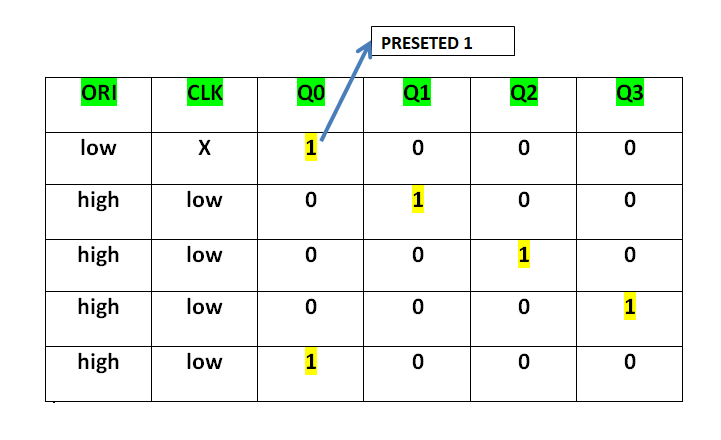
- At FF-0, when PR = 0, the output Q = 1 is generated, and this creates the initial state of the counter.
- At the other flip-flops (FF-1, FF-2, FF-3), the CLR = 0, forcing the outputs Q = 0 at these flip-flops.
- This setup results in Pre-set 1 at FF-0, and the other flip-flops hold 0. This "1" at FF-0 then propagates through the flip-flops in a cyclic manner, creating the sequence that is characteristic of the Ring Counter.
This Preseted 1 is generated by making ORI low and that time Clock (CLK) becomes don't care. After that ORI is made to high and apply low clock pulse signal as the Clock (CLK) is negative edge triggered. After that, at each clock pulse, the preseted 1 is shifted to the next flip-flop and thus forms a Ring. In this way can design a 4-bit Ring Counter using four D flip-flops.
**Types of Ring Counter:
There are two types of Ring Counter:
**Straight Ring Counter
It is also known as One hot Counter. In this counter, the output of the last flip-flop is connected to the input of the first flip-flop. The main point of this Counter is that it circulates a single one (or zero) bit around the ring. Here, we use Preset (PR) in the first flip-flop and Clock (CLK) for the last three flip-flops.

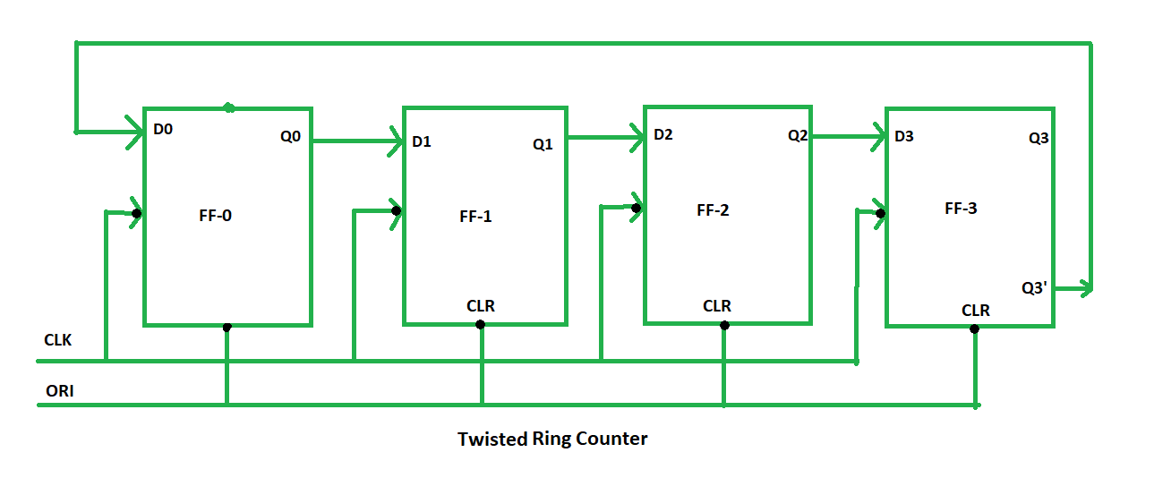
**Twisted Ring Counter
It is also known as a switch-tail ring counter, walking ring counter, or Johnson counter. It connects the complement of the output of the last shift register to the input of the first register and circulates a stream of ones followed by zeros around the ring. Here, we use Clock (CLK) for all the flip-flops. In the Twisted Ring Counter, the number of states = 2 X the number of flip-flops.
**Advantages of Ring Counter
- **Simplicity: It’s easy to design, especially for small applications.
- **Low Resource Use: You don’t need a lot of components compared to other counters.
- **Predictable Output: It will always go through the same set of states in the same order.
- **Easy to Decode: Each state is distinct and easy to decode because it uses one-hot encoding only one output is high at a time.
- **Glitch-Free Output: Since only one flip-flop is active at a time, there's less chance of output glitches, making it more reliable in certain applications.
**Disadvantages of Ring Counter
- **Limited States: You can only cycle through as many states as the number of flip-flops in the counter. So, for a 4-bit counter, you can only have four unique states.
- **Not for Complex Patterns: It’s not great if you need a counter that counts in random or non-binary patterns since it’s limited to the cyclic pattern of shifting one
1through the flip-flops. - **Needs Initialization: A ring counter must be properly initialized (usually with only one flip-flop set to 1) before it starts working. If not, it can get stuck in an invalid state.
- **Hardware Cost Increases: As you add more flip-flops to increase the number of states, the hardware needed also increases, which can make the design bulky for large state requirements.
**Applications of Ring Counter
Ring counters are used when you need a system that goes through a specific, repeating set of states. For example:
- **Sequence Generation: It’s useful when you want a predictable sequence, like in simple control systems or timing circuits.
- **Control Systems: Ring counters are great for things like multiplexers or encoder circuits, where the order of operations needs to follow a certain cycle.
- **Simple Design: Ring counters are easy to design and understand because each state has only one flip-flop set to 1, making debugging and analysis straightforward.
- **Finite State Machines (FSM): Used in systems that move through a known set of states in a loop, such as vending machines or elevator controllers.
- **Shift Register Based Applications: Ring counters are a special type of shift register, so they are used where shift registers are needed for data movement.