What is JK FlipFlop ? (original) (raw)
What is JK Flip-Flop ?
Last Updated : 26 Nov, 2025
What is JK Flip-Flop?
It is one kind of sequential logic circuit which stores binary information in bitwise manner. It consists of two inputs and two outputs. Inputs are Set(J) & Reset(K) and their corresponding outputs are Q and Q'. JK flipflop has two modes of operation which are synchronous mode and asynchronous mode. In synchronous mode, the state will be changed with the clock(clk) signal, and in asynchronous mode, the change of state is independent from its clock signal. Let's see its diagram structure.

The JK flip flop diagram above represents the basic structure which consists of Clock (CLK), Clear (CLR), and Preset (PR).
Below is the circuit diagram of JK Flip Flop. Two 3-input NAND gates are used in place of the original two 2-input AND gates. The outputs at Q and Q' are coupled to each gate's third input. Since the two inputs are now interlocked, the SR flip-flop's cross-coupling enables the previously invalid condition of (S = "1", R = "1") to be employed to perform the "toggle action".

JK Flip Flop
In a circuit "set", the bottom NAND gate interrupts the J input coming from the "0" position of Q'. In the "RESET" state, the top NAND gate interrupts the K input coming from the 0 positions of Q. We can use Q and Q' to control the input because they are always different. The flip flop is toggled according to the truth table when both inputs "J" and "K" are set to 1.
Truth Table of JK Flip Flop
| **Inputs | Outputs | Comments | |||||
|---|---|---|---|---|---|---|---|
| **PR | **CLR | **CLK | **J | **K | **Q(n+1) | **Q'(n+1) | |
| 0 | 1 | NA | NA | NA | 1 | 0 | Set (Preset) |
| 1 | 0 | NA | NA | NA | 0 | 1 | Reset (Clear) |
| 1 | 1 | 0 | NA | NA | Q(n) | Q'(n) | Initial Stage |
| 1 | 1 | 1 | 0 | 0 | Q(n) | Q'(n) | Initial Stage |
| 1 | 1 | 1 | 1 | 0 | 1 | 0 | Set |
| 1 | 1 | 1 | 0 | 1 | 0 | 1 | Reset |
| 1 | 1 | 1 | 1 | 1 | Q'(n) | Q(n) | Toggle |
Characteristic Table
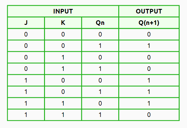
A JK flip-flop is a kind of sequential logic circuit that keeps track of binary data. Its characteristic table shows how the output (Qn+1) changes using inputs (J & K) along with the last state (Qn).
JK Flip Flop Characteristic Table
**Let’s break down the characteristic table. There are four states to understand:
- J = 0, K = 0 (No Change): Here, the output Q(n+1) stays the same. This means the next state (Q(n+1)) is just like the current one (Qn).
- J = 0, K = 1 (Reset State): In this case, the next state is reset to 0 (Q(n+1) = 0), no matter what the current state is (Qn).
- J = 1, K = 0 (Set State): Now, the next state gets set to 1 (Q(n+1) = 1), again, no matter what’s happening in the current state (Qn).
- J = 1, K = 1 (Toggle State): In this state, the output Q(n+1) toggles. So if the current state is set (Qn = 1), it will change to 0 (Q(n+1) = 0). If it’s reset (Qn = 0), then it flips to 1 (Q(n+1) = 1).
Characteristic Equation: K̅Qn + JQ̅n
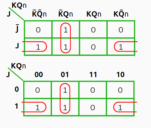
**Group 1: J̅ K̅Qn + JK̅Qn
**Group 2: JK̅Q̅n + JKQ̅n
**Equation: J̅ K̅Qn + JK̅Qn + JK̅Q̅n + JKQ̅n
= (J̅ + J)K̅Qn + JQ̅n(K̅+K) .....(**Distribution Law)
= 1.K̅Qn + 1.JQ̅n .....(**Compliment Law, J̅ + J = 1 and K̅+K = 1)
= **K̅Qn + JQ̅n .....(**Identity Law, 1&A = A )
**Excitation Table
The excitation table shows us which input combinations we should use for a JK flip-flop to get the output we want.
- X - Don't Care
- Qn - Current State
- Q(n+1) - Next State
- J and K - Two input values
Here, X for Don't Care. This means it can be either 0 or 1, & it won't change how the flip-flop works.

This table guides us on what input values to use so we can move from the current (Qn) to the next state (Q(n+1)).
**Let’s look at the transitions
- From **0 to 0: When the current state is 0 (Qn = 0) and you want the next one to stay 0 (Q(n+1) = 0), then set J = 0 & K can be either 0 or 1, which is shown as X (Don’t Care).
- From **0 to 1: If the current state is 0 (Qn = 0) but you want the next state to flip to 1 (Q(n+1) = 1), then J should be set to 1 & K = X (doesn't matter for K).
- From 1 to 0: When you start with a current state of 1 (Qn = 1) & wish for it to switch to 0 (Q(n+1) = 0), then J should be X and K must be set at 1.
- From **1 to 1: If you're at a current state of 1 (Qn = 1) & want it to stay at 1 for the next state (Q(n+1) = 1), then just set J = X and K should be set at 0.
This table is used a lot in circuit design. It helps show the inputs needed to get those desired output transitions.
Applications of JK Flip-Flop
- **Counters: **Counters are very essential components for the application of frequency dividers and event sequencers where there is a need of storing and propagating the count value. We can design binary synchronous and asynchronous counters using JK-flipflop.
- **Shift Registers: For data storage and manipulation, serial-to-parallel or parallel-to-serial data conversion the shift registers are widely used. Registers can store and shift the binary data in a sequential manner. We can design it by JK-flipflops.
- **Memory Units: JK-flipflop itself act as a memory unit to store binary information. By making a sequential chain of JK-flipflops we can use it even as RAM.
Advantages of JK Flip-Flop
- **Versatility: As discussed above, JK-flipflops can be used as a basic memory element or a primary building block of further complex memory design. It is very much adaptive as it can be operated in both synchronous and asynchronous modes.
- **Toggle Functionality: The application which are required to get output as its complement of input that also can be developed by JK-flipflops as when J=K=1 it triggers toggle state which gives output which is complement with it's each clock pulse.
- **Error Detection and Correction: We can use a complex circuit built by JK-flipflops which can detect and correct information during data-transmission.
Disadvantages of JK Flip-Flop
- **Complexity: Compared to other types of flipflops(D,T, SR), JK flipflop requires additional logic gates to implement which consumes extra memory resources and increases complexity to operate.
- **Propagation Delay: This is the major problem present in JK-FF. Propagation delay results a timing delay in certain application which are time-flow sensitive.
- **Race Problem: This issue arises when the clock input's timing pulse isn't given enough time to turn "Off" before the output Q's state is altered.