What is Thyristors in Power Electronics ? (original) (raw)
Last Updated : 23 Jul, 2025
Thyristors in Power Electronics are used as power semiconductor devices which are used as on/off switches in power control circuits. A power semiconductor device is a semiconductor device used as a switch or rectifier in power electronics for example in a switch-mode power supply. A thyristor is the most important type of power semiconductor device. They are extensively used in power electronic circuits. They are operated as bi-stable switches from non-conducting to conducting state. Thyristors are high speed switches that can be used to replace electromechanical relays in many circuits as they have no moving parts, no contact arcing, or suffer from corrosion or dirt. But in addition to simply switching large currents “ON” and “OFF”, thyristors can be made to control the mean value of an AC load current without dissipating large amounts of power.
Table of Content
- What is a Thyristor?
- Properties of Thyristors
- Construction of Thyristor
- Working of Thyristor
- V-I characteristics of thyristor
- Types of Thyristors in Power Electronics
- Examples of Thyristors in Power Electronics
What is a Thyristor?
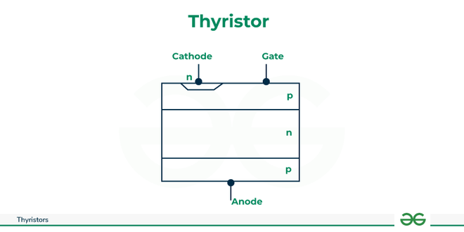
A thyristor is a semiconductor device that works as a switch in electronic circuits. It is a four-layered device with three p-type and one n-type silicon layer. The layers are alternately stacked and connected through a metal electrode. The two p-type layers are connected through a region called the p-n-p-n structure.
- The thyristors are used extensively in power electronic circuits. They are operated as bistable switches, operating from of state to conducting state.
- A thyristor is a four-layer semiconductor device, consisting of alternating P-type and N-type materials (PNPN). A thyristor usually has three electrodes: an anode, a cathode and a gate, also known as a control electrode.
- Thyristor symbol representation is shown below:
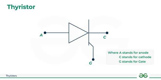
Thyristor-circuit-symbol
The member of the Thyristors family are SCR, LASCR, RCT, GTO, SITH, and MCT. Thyristors are a class of semiconductor devices characterized by 4-layers of alternating p and n material. Four-layer devices act as either open or closed switches; for this reason, they are most frequently used in control applications.
The thyristor is a unidirectional device, which means it can only conduct current in one direction. It has three terminals, an anode, a cathode and a gate. The anode is the positive terminal, the cathode is the negative terminal, and the gate is used to control the flow of current from the anode to the cathode. When a small voltage is applied to the gate, the thyristor turns on, allowing a large current to flow through it.
The most common type of thyristor is the silicon-controlled rectifier (SCR). When the cathode is negatively charged relative to the anode, no current flows until a pulse is applied to the gate. Then, the SCR conducts current until the voltage between the cathode and anode is reversed or reduced below a certain threshold or holding value. Using this type of thyristor, large amounts of power can be switched or controlled using a small triggering current or voltage.
Properties of Thyristors
- It is a unidirectional device
- It Controls DC Power
- It Conducts only one direction
- It have a 3 terminals(Anode, Cathode and Gate)
- It used for medium to high voltage applications
- Its is also known as Silicon Controlled Rectifier
- It has many applications like, it is used in Rectifiers, power supplies, Inverters, Battery charges etc.
Understanding the Role of Thyristors in Power Electronics
Thyristors in Power Electronics plays an important role in electronics in switching on and off quickly, making them ideal for use in high-power applications. Thyristors are used in circuits that require precise control of voltage and current, such as in power supplies, motor drives, and inverters.
In power electronics, thyristors are used in conjunction with other electronic components, such as capacitors, inductors, and diodes, to create complex circuits that can regulate power output. These circuits can be used to control the speed of motors, regulate voltage, and convert DC power to AC power.
Thyristor
Thyristors are used in power control circuits to regulate the amount of power flowing through a circuit. They are used to switch on and off loads such as motors, heaters, and lights. The amount of power flowing through the circuit can be controlled by varying the pulse width of the gate signal.
- Thyristors are semiconductor devices that can operate only in the switching mode.
- Thyristor are current operated devices, a small Gate current controls a larger Anode current.
- Conducts current only when forward biased and triggering current applied to the Gate.
- The thyristor acts like a rectifying diode once it is triggered “ON”.
- Blocks current flow when reverse biased, no matter if Gate current is applied.
- Once triggered “ON”, will be latched “ON” conducting even when a gate current is no
- longer applied providing Anode current is above latching current
Construction of Thyristor
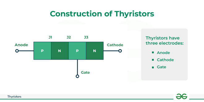
A thyristor is a four-layer semiconductor device, consisting of alternating P-type and N-type materials (PNPN). A thyristor usually has three electrodes: an anode, a cathode and a gate, also known as a control electrode.
- Thyristors have three electrodes: an anode, a cathode and a gate.
- Thyristors are four-layer semiconductors with alternating P-type and N-type materials.
Construction-of-Thyristor
- The 4-layer diode (or Shockley diode) is a type of thyristor that acts something like an ordinary diode but conducts in the forward direction only after a certain anode to cathode voltage called the forward-breakover voltage is reached.
- The 4-layer diode has two leads, labeled the anode (A) and the cathode (K).
- The symbol reminds you that it acts like a diode. It does not conduct when it is reverse-biased.
- The SCR had its roots in the 4-layer diode. By adding a gate connection, the SCR could be triggered into conduction. The SCR is the most widely used thyristor. It can switch very large currents on and off.
Working of Thyristor
A thyristor also can function as a circuit breaker in device power circuits. They prevent power supply disruptions by connecting a Zener diode at the thyristor gate. When power supply voltage levels exceed the Zener voltage, the thyristor turns off the power supply output to the ground and activates circuit breakers or fuses upstream from the power supply. This is called a crowbar effect and protects devices being served by the power supply from damage.
- Thyristors operate in one of the following three states, depending on the requirements:
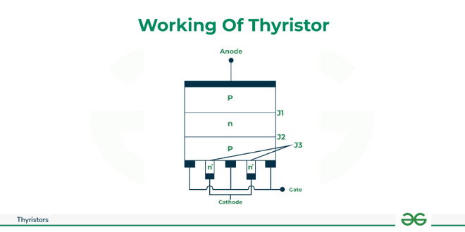
- Thyristors consists of four layers(i.e., p, n, p and n) three terminals A(Anode), K(Cathode) and G(Gate) and three junction J1 , J2 , and J3.
- In thyristors there are three junctions J1, J2 and J3 .
- These junctions play a very important role in the operation of thyristor.
- Depending on whether the junctions are forward biased or reverse biased, the thyristor will either conduct the current or will not be conduct. For thyristor to conduct current, all the three junctions must be forward biased. If any one of the junctions is reverse biased the thyristor will not conduct any current and hence acts as an open switch.
Working-of-Thyristor
**Reverse Blocking
- Current attempts to pass through the thyristor in the opposite direction. However, a diode blocks it, and the thyristor is not activated.
- In this case, the junction J1 and J3 are reverse biased, whereas J2 is forward biased. Hence, thyristor does not conduct and acts as an open switch.
**Forward Blocking
- The thyristor blocks the flow of current, despite voltage being applied in the direction that would signal a diode to conduct it.
- In this case, the junction J2 is reverse biased, whereas junctions J1 and J3 are forward biased, again due to which the thyristor does not conduct and acts as an open switch.
**Forward Conduction
- This is a thyristor's primary operating mode. It is switched to conducting mode and stays that way until the current falls below a specific level, called the holding current.
- In this case, all the three junctions are forward biased and hence gets turned ON and starts conducting. Here, the thyristor acts as a closed switch.
Hence, from the above cases, it is clear that all the three junctions play important role in the operation of thyristor and they all must be forward biased in order to turn ON the thyristor.
V-I characteristics of thyristor
The V-I characteristics of thyristor is a graph between the anode current IA and the anode-cathode voltage VA for different values of gate current IG. This characteristics can be drawn by considering the basic operation of the thyristor. The below figure shows the V-I characteristics which is also called as static-cathode characteristics. It basically consist of three regions, They are:
- Region 1
- Region 2
- Region 3

VI-characteristics-of-Thyristor
Region 1
- When the positive terminal of the supply is connected to cathode and the negative terminal is connected to anode with gate circuit open then thyristor operates in region 1. In this region junction J1 and J3 becomes reverse biased, whereas the junction J2 becomes forward biased. The reverse biased junctions (J1 and J3) acts as open circuit and the forward biased junction(J2) acts as a short circuit, as shown in figure.
Region 2
- When the positive terminal of the supply is connected to anode and the negative terminal is connected to cathode with gate circuit open then thyristor operates in region 2. In this region junction J1 and J3 becomes forward biased, whereas the junction J2 gets reverse biased. The forward biased junctions (J1 and J3) acts as short circuit and the reverse biased junction(J2) acts as a open circuit, as shown in figure. Even in this region, the thyristor does not conduct any current expect a very small value of the leakage current. This mode of thyristor is called as forward blocking mode. Just as the region 1, i. e., reverse blocking mode, the thyristor can be made to conduct in the forward blocking mode by increasing the anode-cathode voltage to a value called as forward breakdown voltage(VBO). Even this method is not recommended as it may also damage the thyristor. Hence, the thyristor does not conduct even in this mode and is treated as open switch.
Region 3
- When the positive terminal of the supply is connected to anode and the negative terminal to cathode with gate circuit closed the operates in region 3. In this region, all the three junctions (J1, J2 and J3) act as short circuit shown in figure and hence conducts current. In this region thyristor is said to be in a forward conduction mode and hence acts as a closed switch. This method of conducting the thyristor is the most efficient, as it requires a voltage which is very much less than VBO. The only extra thing we require is a gate signal for a small period of latching current. Once the anode current attains this value, the gate losses the control and hence can be removed. The removal of the gate signal will not have any effect on the thyristor conduction. However, if the anode current decreases to a value called ad holding current, the thyristor will once again go back to the forward blocking gate. Hence, care must be taken that, the anode current should not drop below the holding current after the gate signal is removed.
Turn off and Turn on characteristics
These characteristics are discussed below of thyristor as follows:
Turn ON Switching Characteristics of thyristor
A forward biased thyristor is turned ON by applying a positive gate voltage between the gate and the cathode, as shown in figure(1).
Figure(2) , shows the waveforms of the gate current(IG), anode current(IA) and anode to cathode voltage(VAK). The total switching period being much smaller compared to the cycle time, IA and VAK before and after switching will appear flat.
As shown in figure , there is a transition time “T-off” from forward OFF state to forward ON state. This transition time is called the thyristor turn ON time and can be divided into three separate intervals namely, They are
- Delay time (Td)
- Rise time (Tr)
- Spread time ( Tp)

Turn-ON-Switching-Characteristics-of-thyristor
**Delay Time (Td)
It is the time between the instant at which the gate current reaches 90% of its final value and the instant at which the anode current reaches 10% of its final value. It is the time taken by the anode voltage to fall from VAK to 0.9 VAK
**Rise Time (Tr)
For a resistive load, “rise time” is the time taken by the anode current to rise from 10% of its final value to 90% of its final value. At the same time, the voltage VAK falls from 90% of its initial value to 10% of its initial value. However, current rise and voltage fall characteristics are strongly influenced by the type of the load. For inductive load the voltage falls faster than the current. While, for a capacitive load, current rises rapidly.
**Spread Time ( Tp)
It is the time taken by the anode current to rise from 90% of its final value to 100%. During this time conduction spreads over the entire cross-section of the cathode of the thyristor. The spreading interval depends on the area of the cathode and on the gate structure of the thyristor.
Turn OFF Switching Characteristics of thyristor
- Once the thyristor is ON and its anode current is above the latching current level, the gate losses control. It can be turned OFF only by reducing the anode current below the holding current. The OFF time tq of a thyristor is defined as the time between the instant anode current becomes zero and the instant the thyristor regains forward blocking capability. If forward voltage is applied across the device, during this period the thyristor turns ON again.
- During turn OFF time, excess minority carriers from all the four layers of the thyristor must be removed. Accordingly, tq is divided into two intervals, the reverse recovery time(tRR) and the gate recovery time(tGR), figure shows the variation of the anode current and the anode to cathode voltage with time during turn OFF operation for an applied sinusoidal voltage(VI).
.png)
Turn-OFF-Switching-Characteristics-of-thyristor
- The anode current becomes zero at time t1 and starts growing in the negative direction with the same DiA / Dt till time t2. This negative current removes excess carriers from the junctions J1 and J3. At time t2 excess carriers densities at these junctions are not sufficient to maintain the reverse current. The value of the anode current at time t2 is called as the reverse recovery current(IRR). The reverse anode current reduces to the level of reverse saturation current. The total charge removed from the junctions between t1 and t3 is called the reverse recovery charge(QRR). Fast decaying reverse current during the interval t2 – t3 coupled with the di / dt limiting inductor may cause a large reverse voltage spike to appear across the device. This voltage must be limited below the VRRM rating of the device. Up to time t2 the voltage across the device(VAK) does not change substantially from its state value. However, after the reverse recovery time, the thyristor regions the reverse blocking capacity and VAK starts following the supply voltage. At the end of the reverse recovery period(trr) trapped charges still exist at the junction J2 which prevents the device from blocking forward voltage just after trr. These trapped charges are removed only by the process of recombination. The time taken for this recombination process to complete between t3 and t4 is called the gate recovery time(tgr). The time interval tq = trr + tgr is called “device turn OFF time” of the thyristor.
- No forward voltage should appear across the device before the time tq in order to avoid its inadvertent turn ON. While designing an thyristor circuit, one must provide a time interval (tc > tq) during which a reverse voltage is applied across the device, where tc is the circuit turn OFF time.
Types of Thyristors in Power Electronics
There are three types of Thyristors in Power Electronics
- Discrete Plastic
- Plastic Module
- Press Pack
Discrete Plastic
A Discrete Plastic thyristor alludes to an individual thyristor bundled in a plastic lodging. This bundling gives a defensive and protecting nook for the semiconductor gadget, making it reasonable for different electronic applications. Here are a few vital highlights and qualities of a Discrete Plastic thyristor
**Construction of Discrete Plastic
**Semiconductor Layers: Like other thyristors, a Discrete Plastic thyristor comprises of exchanging layers of p-type and n-type semiconductor materials, shaping a P-N-P-N structure.
**Gate Design: The thyristor incorporates a gate structure, commonly made of metal or one more conductive material, put between the anode and cathode.
**Packaging of Discrete Plastic
- **Plastic Enclosure: The semiconductor gadget is housed in a plastic bundle that gives mechanical security, electrical insulation, and ecological isolation.
- **Lead Design: The plastic package has leads for external associations. Normal lead setups incorporate TO-92, TO-220, or other industry-standard packages.
Plastic Module
A Plastic Module thyristor alludes to a thyristor semiconductor gadget that is epitomized in a plastic module for security and simplicity of reconciliation into electronic circuits. This kind of bundling joins the vigor of module-style bundling with the advantages of a plastic nook. Here are key elements and qualities of a Plastic Module thyristor
**Construction of Plastic Module
**Semiconductor Layers: Like other thyristor s, a Plastic Module thyristor comprises of layers of p-type and n-type semiconductor materials organized in a P-N-P-N structure.
**Gate Structure: The thyristor module incorporates a door structure, frequently made of metal or one more conductive material, situated between the anode and cathode for controlling conduction.
Packaging of Plastic Module
- **Plastic Module Enclosure: The semiconductor gadget is housed in a module-style plastic bundle that gives security against ecological variables, mechanical burdens, and electrical protection.
- **Lead Design: The module normally includes terminal leads or pins that work with simple association with outside circuits. The lead setup relies upon the particular module plan.
- **Module Size and Form Factor: The plastic module bundling can differ in size and structure factor, contingent upon the power rating, expected application, and industry norms.
Press Pack
A Press Pack thyristor alludes to a thyristor semiconductor gadget that is typified in a powerful and strong press pack lodging. The press pack configuration offers mechanical help and warm administration, making it reasonable for high-power and high-voltage applications. Here are key elements and qualities of a Press Pack thyristor
C**onstruction of Press Pack
**Semiconductor Layers: Like other thyristor s, a Press Pack thyristor comprises of layers of p-type and n-type semiconductor materials organized in a P-N-P-N structure.
**Gate Structure: The thyristor incorporates an entryway structure, frequently made of metal or one more conductive material, situated between the anode and cathode for controlling conduction.
**Packaging of Press Pack
- **Press Pack Enclosure: The semiconductor gadget is housed in a press pack, which is an unbending, generally metal, nook that offers mechanical help and warm dispersal.
- **Cooling Components: Press pack thyristor modules frequently incorporate cooling components, for example, heat sinks or other warm administration parts to disperse the intensity created during activity.
- **Terminal Leads: The module highlights terminal leads or pins that work with simple association with outside circuits. The lead setup relies upon the particular module design.
Examples of Thyristors in Power Electronics
There are some commonly used examples of thyristors in Power Electronics :
- Silicon-Controlled Rectifier (SCR)
- TRIAC
- Gate Turn-Off Thyristor (GTO)
Silicon-Controlled Rectifier (SCR)
One of the most popular example of thyristors is this one. It is a solid-state device with four layers that only permits one direction of current flow. Power control applications such as motor speed control, light dimming, power supplies, etc. frequently use thyristors.
V-I characteristics of SCR
The V-I characteristics of SCR is a graph between the anode current IA and the anode-cathode voltage VA for different values of gate current IG. This characteristics can be drawn by considering the basic operation of the SCR. The below figure shows the V-I characteristics which is also called as static-cathode characteristics. It basically consist of three regions, They are
- Region 1
- Region 2
- Region 3
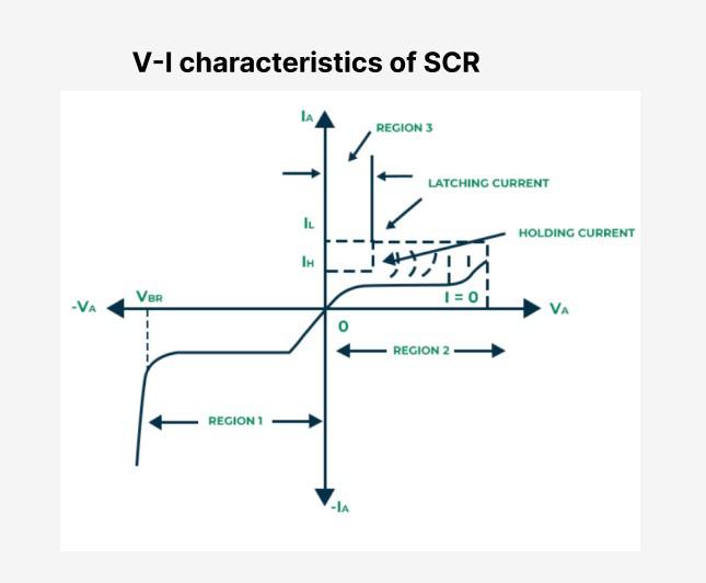
Region 1
- When the positive terminal of the supply is connected to cathode and the negative terminal is connected to anode with gate circuit open then SCR operates in region 1.
- In this region junction J1 and J3 becomes reverse biased, whereas the junction J2 becomes forward biased.
Region 2
- When the positive terminal of the supply is connected to anode and the negative terminal is connected to cathode with gate circuit open then SCR operates in region 2.
- In this region junction J1 and J3 becomes forward biased, whereas the junction J2 gets reverse biased. The forward biased junctions (J1 and J3) acts as short circuit and the reverse biased junction(J2) acts as a open circuit, as shown in figure.
- Even in this region, the SCR does not conduct any current expect a very small value of the leakage current. This mode of SCR is called as forward blocking mode.
Region 3
- When the positive terminal of the supply is connected to anode and the negative terminal to cathode with gate circuit closed the SCR operates in region 3.
- In this region, all the three junctions (J1, J2 and J3) act as short circuit shown in figure and hence conducts current. In this region SCR is said to be in a forward conduction mode and hence acts as a closed switch.
TRIAC
TRIAC is an example of a semiconductor device with three terminals that can conduct current in both directions is called a TRIAC. It is extensively utilized in AC power control applications, including light dimmer switches, small motor speed control, and appliance heating control.
V-I Characteristics of TRIAC
TRIAC is comprised of two SCRs in backwards equal. It works in four modes. At first the TRIAC works in forward and turn around impeding mode and just little spillage current moves through it. At the point when the applied voltage at the MT2 terminal is additionally expanded and when it crosses the breakover voltage TRIAC begins conduction. The ongoing begin to flow and the voltage applied at the gate terminal controls this current flow.
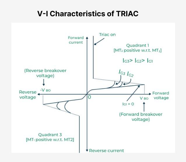
First Quadrant (I)
- In this quadrant, both MT1 (Main Terminal 1) and MT2 (Mian Terminal 2) are positive concerning the gate terminal.
- At the point when a positive voltage is applied to the gate terminal concerning MT2, the TRIAC becomes forward-one-sided, permitting current to flow.
- The TRIAC conducts during the positive half-cycle of the AC waveform.
**Second Quadrant (II)
- MT1 is negative, and MT2 is positive concerning the gate terminal.
- Applying a positive voltage to the gate terminal as for MT1 triggers the TRIAC to lead.
- The gadget conducts during the negative half-cycle of the AC waveform.
**Third Quadrant (III)
- Both MT1 and MT2 are negative concerning the gate terminal.
- A negative voltage applied to the entryway terminal as for MT2 makes the TRIAC lead during the positive half-cycle.
- This quadrant permits control of force in the negative half-pattern of the AC waveform.
Fourth Quadrant (IV)
- MT1 is positive, and MT2 is negative concerning the gate terminal.
- A negative voltage applied to the entryway terminal regarding MT1 makes the TRIAC lead during the negative half-cycle.
- This quadrant empowers control of force in the positive half-pattern of the AC waveform.
Gate Turn-Off Thyristor (GTO)
Gate Turn-Off Thyristor (GTO) is an example of Thyristors that can be turned off by applying a negative voltage pulse to their gate terminal are known as gate turn-off (GTO) thyristors. Because of this feature, they can be used in high-power applications such as power converters, motor drives, and traction control.
V-I characteristics of GTO
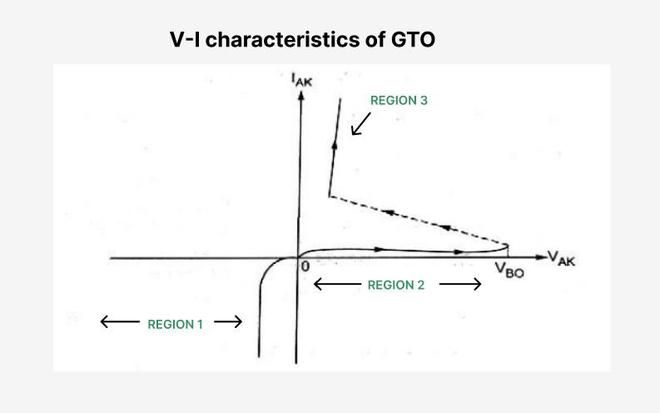
- The V-I characteristics of GTO in forward direction are similar to that of SCR.
- But in reverse direction GTO has virtually no blocking capability.
- Observe that GTO starts conducting in reverse direction after very small reverse (20 to30 V) voltage. This is because of the anode short structure.
Applications of Thyristors
Thyristors can support high voltages and contain a simplified approach to switching the on and off states. So that thyristors has many applications:
- Thyristors are used in speed controls;
- Thyristors are used in light dimmers
- Thyristors are used in Rectifiers
- Thyristors are used in power supplies
- Thyristors are used in Inverters
- Thyristors are used in Battery charges
- Thyristors are used in camera flashes
- Thyristors are used in various types of circuits, such as logic and timer circuits.
Advantages of Thyristors
Thyristors have become standard components because they offer several advantages. These include:
- Fast switching speed
- Good thermal stability
- Low conduction losses
- High reliability
- Speed and the ability to switch currents in microseconds
- Ability to control high voltages and high levels of power
- Lack of moving parts and high reliability
- Ability to control direct current devices, not just routine alternating current
- Quick and easy activation
Disadvantages of Thyristors
- Gate triggering can be sensitive to noise.
- Unidirectional conduction.
- Potential for voltage spikes.
- Lack of inherent turn-off capability.
- Limited frequency response.
- Higher cost compared to some alternatives.
Conclusion
In this article we have learnt about Thyristors in Power Electronics ,the thyristors are used extensively in power electronic circuits. They are operated as bistable switches, operating from of state to conducting state. The member of the Thyristors family are SCR, LASCR, RCT, GTO, SITH, and MCT. Devices using alternating current can be turned on and off by sending a signal to the control gate. This device is called a gate turn-off, or GTO, thyristor. Previously, thyristors needed the current to be reversed to turn off, making them difficult to use with direct current systems. Thyristors are useful in switching applications because they can be fully on or off. This two-state capability differs from transistors, which operate in between on and off states, waiting for a signal to conduct current. We have seen the properties of thyristors and we have the applications and advantages and disadvantages of thyristors in this article.