Control Systems Controllers (original) (raw)
Last Updated : 9 Mar, 2026
Control systems are used to regulate the behavior of dynamic systems in engineering and automation applications. A controller is the main component that processes system error and generates a control action to maintain the desired output.
Controller
A device or algorithm that regulates the behavior of a system by comparing the desired output (setpoint) with the actual output. The difference between these two values produces an error signal.
- The controller processes this error and generates a control signal that adjusts the system input to achieve the desired performance.
- Controllers are widely used in industrial automation, robotics, aerospace systems, and automotive control systems.
Block Diagram
A visual representation that illustrates the components and their interactions within control system. It helps in understanding how the controller processes input signals and generates output signals to control a system.

- **Input Signal: Represents the desired value or reference signal that the system should achieve. It is also known as the setpoint.
- **Summing Junction: Compares the reference input with the feedback signal from the system. The difference between these signals produces the error signal.
- **Controller: Processes the error signal using a control algorithm and generates a control action to reduce the error.
- **Actuating Signal: Output signal produced by the controller. It is used to adjust or manipulate the system being controlled.
- **System or Process: The physical process that needs to be controlled. The actuating signal from the controller is applied to this system.
- **Output: The final response produced by the system or plant after applying the control signal.
- **Feedback Signal: Represents the actual output of the system. It is sent back to the summing junction to continuously monitor system performance.
Types
The types of controllers are as follows:
- Proportional Controller (P-Controller)
- Integral Controller (I-Controller)
- Derivative Controller (D-Controller)
Proportional Controller (P-Controller)
Produces an output that is directly proportional to the error signal. The controller continuously adjusts the control output based on the magnitude of the error.
Mathematical Expression
The control output (u(t)) is calculated as:
u(t) = K_p \times e(t)
where,
K_p = Proportional Gain
e(t) = Error Signal
- The Proportional Controller aims to reduce the error and bring the system closer to setpoint.
- It is effective in reducing steady-state error but may lead to oscillations and overshoot in response.
**Advantages
- **Simple and Easy to Implement: Proportional control is easy to design and implement because it only requires multiplying the error by a constant gain K_p
- **Provides Fast Response: It reacts quickly to changes in the system error, helping the system respond faster to reach the desired output.
- **Reduces Steady-State Error: Proportional control decreases the steady-state error compared to systems without feedback control.
**Disadvantages
- **Cannot Completely Eliminate Steady-State Error: Even with proportional control, a small steady-state error usually remains in the system.
- **May Cause Oscillations or Overshoot if Gain is High: If the proportional gain K_p s too large, the system may become unstable, causing oscillations or overshoot in the output.
Block Diagram of P Controller
Features a direct connection from input to the controller in which then directly influences the output.
- The P-controller multiplies the error signal is difference between the desired setpoint and the actual process variable by constant proportional gain (K_p).
- The resulting control signal is added to system input to correct the error.

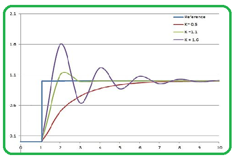
Response Characteristics
The P-controller reduces the steady-state error but introduces the oscillations and overshoot. It cannot eliminate all error.
Integral Controller (I-Controller)
Responds to cumulative sum of past errors. It continuously adjusts the control output to eliminate any steady-state error. The Integral Controller produces an output that is the integral of the error signal with respect to time.
Mathematical Expression
The control output is calculated as:
u(t) = K_i \int e(t)\,dt
where,
K_i = Integral gain
- The Integral Controller helps in the eliminating steady-state error by continuously integrating past errors.
- It ensures that the system reaches and maintains setpoint over time.
**Advantages
- **Eliminates Steady-State Error: Integral control removes the steady-state error by integrating the error over time and adjusting the control signal accordingly.
- **Improves Accuracy of the System: By continuously correcting accumulated errors, it increases the overall accuracy of the system output.
**Disadvantages
- **Slower Response: Integral control reacts slowly because it depends on the accumulation of error over time.
- **May Cause Overshoot if Not Tuned Properly: If the integral gain is too high, the system may overshoot the desired value and become unstable.
Block Diagram of I Controller
Features an integration block between input and the controller.

- The I-controller integrates the error signal over time multiplying it by constant integral gain (K_i).
- This accumulated error correction is added to control signal and gradually eliminating steady-state errors.
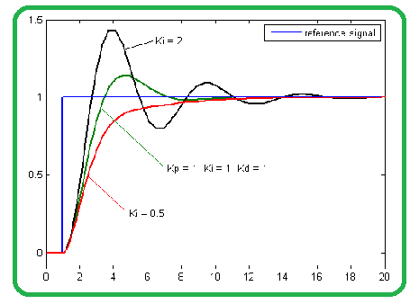
Response Characteristics
The I-controller eliminates steady-state error but can lead to the slower responses and overshoot if not tuned properly.
Derivative Controller (D-Controller)
Reacts to rate of change of the error signal. It anticipates future error trends and provides control action to the counteract them. The Derivative Controller produces an output that is derivative of the error signal with the respect to time.
Mathematical Expression
The control output is calculated as:
u(t) = K_d \frac{de(t)}{dt}
where,
K_d : Derivative gain
- The Derivative Controller helps in the damping oscillations and improving system stability.
- It is anticipates future errors based on the rate of change of error.
Advantages
- **Provides Rapid Response to Changing Errors: Derivative control responds quickly to the rate of change of error, allowing the system to react faster to sudden changes.
- **Reduces Overshoot and Oscillations: It predicts the future trend of the error and helps dampen oscillations, reducing overshoot in the system response.
Disadvantages
- **Amplifies Noise and Measurement Errors: Derivative control is sensitive to small fluctuations in signals, which can amplify noise in the system.
- **Sensitive to Parameter Variations: Changes in system parameters can significantly affect the performance of derivative control, making it less robust if not tuned properly.
Block Diagram of D Controller
Features a differentiation block between input and the controller.
- The D-controller calculates the rate of change of error signal (derivative) and multiplies it by a constant derivative gain (K_d ).
- This derivative term is added to control signal and helping to reduce overshoot and dampen oscillations.

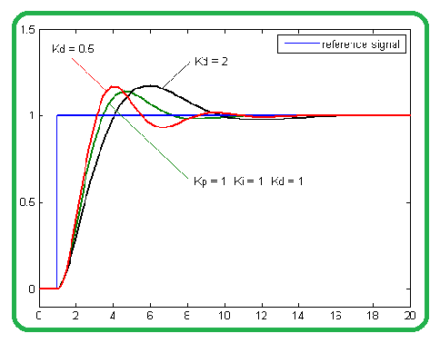
Response Characteristics
The D-controller improves system stability and transient response reducing overshoot and oscillations.
Combinations of Controllers
In practical control systems, controllers are often combined to improve performance. Some of the combinations of controllers are :
Proportional-Integral (PI) Controller
The PI Controller combines the proportional and integral controllers.
The control output is: u(t) = K_p e(t) + K_i \int e(t)\,dt
It reduces steady-state error while maintaining system stability.
Proportional-Derivative (PD) Controller
The PD Controller combines the proportional and derivative controllers.
The control output is: u(t) = K_p e(t) + K_d \frac{de(t)}{dt}
It improves system stability without the significantly affecting steady-state error.
Proportional-Integral-Derivative (PID) Controller
The PID Controller combines the proportional, integral and derivative controllers.
The control output is: u(t) = K_p e(t) + K_i \int e(t)\,dt + K_d \frac{de(t)}{dt}
It provides a balance between reducing steady-state error and damping oscillations.
Applications
The Controllers are widely used in various fields:
- **Industrial Automation: Controllers regulate manufacturing processes and operate industrial machinery automatically.
- **Aerospace: Flight control systems, autopilots, and navigation mechanisms rely on controllers for stable operation.
- **Automotive: Controllers manage vehicle functions such as cruise control, engine management, and anti-lock braking systems.
- **Robotics: Robot movement, positioning, and autonomous navigation are controlled using feedback controllers.
- **Home Automation: Used in temperature control systems, smart devices, and HVAC systems.
Primary Terminologies of Controllers
- **Control System: A system designed to regulate the behavior of another system or process.
- **Controller: A device or algorithm that regulates system output based on feedback.
- **Plant: The physical system or process being controlled.
- **Setpoint: The desired target value of the controlled variable.
- **Controlled Variable: The parameter of the system that must be maintained at a desired value.
- **Feedback: The process of measuring system output and sending it back to the controller.
- **Open Loop Control System: A system where the control action does not depend on feedback.
- **Closed Loop Control System: A system that uses feedback to adjust the control action.
Step-by-Step Process of Controllers
The step by step process of controller are:
Define Control Objectives
- Clearly outline the objectives of control system. What is the system intended to achieve or regulate?
- To Specify performance criteria such as setpoint values, accuracy and response time.
System Modeling
- Develop a mathematical model of system you intend to control.
- To create a representation that describes the relationship between the inputs and outputs. This could be a transfer function and state-space representation or a block diagram.
Choose Controller Type
- Select the appropriate type of controller based on system's characteristics and control objectives.
- The common controller types include Proportional-Integral-Derivative (PID), Proportional-Integral (PI) and Proportional-Derivative (PD) controllers.
Controller Tuning
- Adjust the controller's parameters to achieve the desired system response.
- The tuning may involve manual adjustment, trial and error or automated methods, depending on complexity of the system.
Feedback Loop Design
- Implement a feedback loop that continuously monitors the system's output and compares it to the desired setpoint.
- The error signal generated from this comparison is used as input to the controller.
Controller Implementation
- Once the controller type and tuning parameters are finalized, implement the controller.
- Implementation can be done in the hardware or software.
System Simulation and Testing
- Simulate the control system in controlled environment before deploying it in the real-world applications.
- Test the system's performance under various scenarios to ensure it meets control objectives.
Iterative Tuning
- After initial testing iterate on controller tuning if necessary.
- The Fine-tune controller parameters such as proportional gain and derivative gain based on the simulation and real-world results.
Real-World Deployment
- Deploy the control system in the actual environment where it will regulate the desired process or system.
- Continuously monitor its performance during this phase.
Feedback and Optimization
- To Gather data and feedback from control system's operation in the field.
- Optimize controller parameters and system settings based on the real-world data.
Maintenance and Upkeep
- Regularly maintain and service the control system to ensure it operates reliably.
- Adapt the control system to the changing conditions if necessary to maintain control objectives.
Documentation
- Maintain comprehensive documentation of control system design including controller parameters and tuning procedures.
Example
**Cruise Control in Vehicles:

The cruise control is a classic example of a closed-loop control system. The driver sets a desired speed and controller adjusts the throttle or engine power based on feedback from the speed sensors to maintain the set speed.
- **Speed Sensor: Measures the actual vehicle speed.
- **Reference Speed: Desired speed set by the driver.
- **Error Signal: Difference between reference speed and actual speed.
- **Controller: Adjusts engine power to minimize the error.