Ohm's Law (original) (raw)
Last Updated : 30 May, 2026
Ohm’s law states that Current is directly proportional to the potential difference across a conductor, provided temperature and other physical conditions remain constant. It describes the fundamental relationship between voltage and current in an electric circuit.
V \propto I
\boxed{ V= I \times R }
where,
- **R is the Constant of Proportionality known as Resistance,
- **V is the Voltage applied, and
- **I is the current flowing through the electrical circuit.
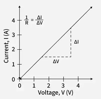
Graph
The graph between voltage and current for an ohmic conductor is a straight line passing through the origin, showing that the current is directly proportional to the applied voltage when the temperature remains constant.
Ohm’s Law Unit
The three main physical quantities associated with Ohm’s Law are voltage, current, and resistance. The table below shows their symbols and SI units:
| Physical Quantity | Unit of Measurement | Unit Abbreviation |
|---|---|---|
| Current (I) | Ampere | A |
| Voltage (V) | Volt | V |
| Resistance (R) | Ohm | Ω |
Ohm’s Law Equations
Ohm’s law provides three equations, which are
- V = I × R
- I = V / R
- R = V / I
Where,
- **V is the voltage,
- **I is the current, and
- **R is the resistance.
Vector Form
The relation between current and voltage is established by, Ohm's law, and its vector form is,
{\vec{J} = σ\vec{E}}
Where,
- \bold{\vec{J}} is Current Density vector,
- \bold{\vec{E}} is Electric Field vector, and
- **σ is conductivity of material.
Resistivity
The hindrance faced by the electrons while moving in any material is called the resistivity of the material.
Let a resistor of a length of 'l' and a cross-sectional area of 'A' have a resistance be R. Then we know,
Resistance is directly proportional to the length of the resistor, i.e. R ∝ l. . (1)
Resistance is inversely proportional to the cross-section area of the resistor, i.e. R ∝ 1/A.. . (2)
combining eq. (1) and eq. (2)
R = \frac{ρl}{A}
Where **ρ is the proportionality constant called coefficient of resistance or resistivity.
Now if L = 1 m and A = 1 m2, in the above formula we get,
R = ρ
This means for a resistor of length 1 m and cross-section area 1 m, the resistance is called the resistivity of the material.
Experimental Verification
Verification of Ohm's Law is achieved by performing the following experiment.
Apparatus Required
The apparatus required for performing the experiment for the Verification of Ohm's Law is,
- Resistor
- Ammeter
- Voltmeter
- Battery
- Plug Key
- Rheostat
Circuit Diagram
The circuit diagram for the Experimental Verification of Ohm's Law is given in the diagram below.
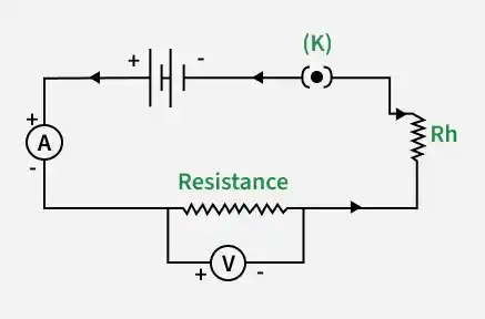
- The key K is closed initially and the rheostat is adjusted such that the reading in ammeter A and voltmeter V is minimum.
- The current is then increased in the circuit by adjusting the rheostat, and the current at various values of the rheostat and their respective voltage is recorded.
- Now for different values of voltage(V) and current(I) and then calculate the ratio of V/I.
- After calculating all the ratios of V/I for different values of voltage and current, we notice that the value is almost constant.
- Now plotting a graph of the current against the potential difference we get a straight line. This shows that the current is directly proportional to the potential difference and its slope is the resistance of the wire.
Pie Chart
To better understand the relationship between various parameters, we can take all the equations used to find the voltage, current, resistance, and power and condense them into a simple Ohm’s Law pie chart as shown below:
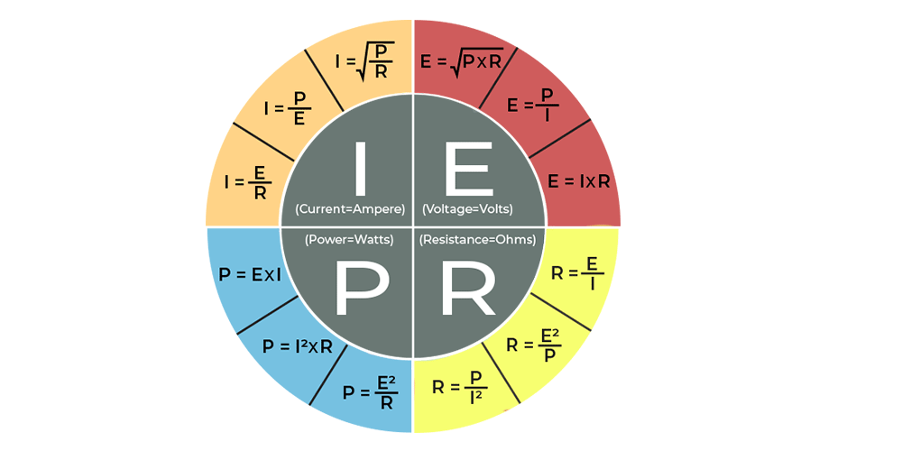
Ohm's Law Pie Chart
Matrix Table
Like the Ohm's Law Pie Chart shown above, we can condense the individual Ohm’s Law equations into a simple matrix table as shown below for easy reference when calculating an unknown value.
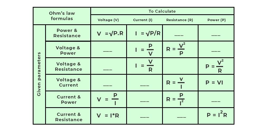
Ohm's Law Matrix Table
Applications
- It also simplifies power calculations.
- To keep the desired voltage drop between the electrical components, Ohm's law is employed.
- An electric circuit's voltage, resistance, or current must be determined.
- Ohm's law is also utilized to redirect current in DC ammeters and other DC shunts.
Limitations of Ohm's Law
- The law of Ohm does not apply to unilateral networks. The current can only flow in one direction in unilateral networks. Diodes, transistors, and other electronic components are used in these sorts of networks.
- Non-linear components are also exempt from Ohm's law. Non-linear components have a current that is not proportional to the applied voltage, which implies that the resistance value of those elements varies depending on the voltage and current. The thyristor is an example of a non-linear element.
Solved Problems
**Question 1: Find the resistance of an electrical circuit with a voltage supply of 15 V and a current of 3 mA.
**Solution: Given:
V = 15 V,
I = 3 mA = 0.003 A
The resistance of an electrical circuit is given as:
⇒ R = V / I
⇒ R = 15 V / 0.003 A
⇒ R = 5000 Ω
⇒ R = 5 kΩHence, the resistance of an electrical circuit is 5 kΩ.
**Question 2: If the resistance of an electric iron is 10 Ω and a current of 6 A flows through the resistance. Find the voltage between two points.
**Solution: Given:
I = 6 A, R = 10 Ω
The formula to calculate the voltage is given as:
V = I × R
⇒ V = 6 A × 10 Ω
⇒ V = 60 VHence, the voltage between two points is 60 V.
**Question 3: Find the current passing through the conductor drawing 20 volts when the power drawn by it is 60 watts.
Solution: According to Ohm’s P = VI
Given P = 60 watt, V = 20 volt
⇒ I = P/V
⇒ I = 60/20
⇒ I = 3 AHence, the current flowing through the conductor is 3 A
**Question 4: A battery of 6 V is connected to the bulb of resistance 4 Ω. Find the current passing through the bulb and the circuit's power.
**Solution: Given,
V = 6 V
R = 4 ΩWe know that,
V = IR (Ohms Law)
⇒ 6 = 4I
⇒ I = 6 ÷ 4 = 1.5 A
⇒ I = 1.5 A
Thus, the current flowing through the bulb is 1.5 A
For the Power of the circuit
P = VI
⇒ P = (6)(1.5)
⇒ P = 9 watt
Thus, the power of the circuit is 9 watts.
Unsolved Problems
**Question 1: A resistor has a resistance of 8 Ω, and a voltage of 24 V is applied across it. Find the current flowing through the resistor.
**Question 2: A current of 2 A flows through a conductor when a voltage of 10 V is applied. Find the resistance of the conductor.
**Question 3: If a resistance of 5 Ω is connected to a battery of 20 V, calculate the current flowing in the circuit.
**Question 4: A current of 4 A flows through a conductor having a resistance of 3 Ω. Find the voltage across the conductor.
**Question 5: A circuit carries a current of 0.5 A when connected to a voltage of 12 V. Determine the resistance of the circuit.