Transformer (original) (raw)
Last Updated : 23 Jul, 2025
**A transformer is the simplest device that is used to transfer electrical energy from one alternating-current circuit to another circuit or multiple circuits, through the process of electromagnetic induction. A transformer works on the principle of **electromagnetic induction to step up or step down the voltage.
A transformer either increases AC voltage (Step-up transformer) or decreases AC voltage (Step-down transformer). A transformer, which is normally utilized in the transmission and distribution of alternating current power, is fundamentally a voltage control device. Transformers are used for a wide range of purposes, including increasing the voltage from electric generators to enable long-distance transmission of electricity and decreasing the voltage of conventional power circuits to run low-voltage devices like doorbells and toy electric trains.
What is a Transformer?
A transformer is a static electrical device that transmits AC power from one circuit to another at a constant frequency, but the voltage level may be changed, implying the voltage can be increased or decreased depending on the requirement.
Types of Transformer
**Transformer types based on Voltage Level:
**There are primarily two types of Transformer based on the operating voltage. The following are some of them:
Types of Transformer
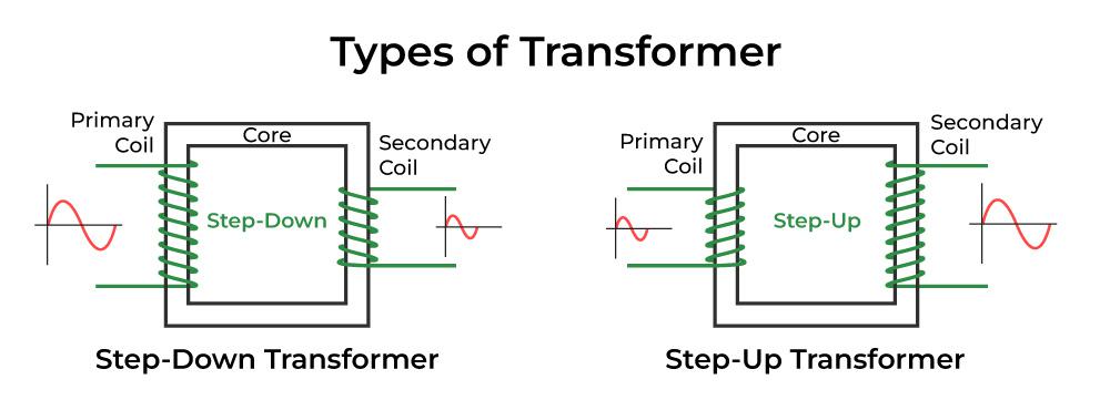
**Step-down Transformer:
- The primary voltage is converted to a lower voltage across the secondary output using a step-down transformer.
- The number of windings on the primary side of a step-down transformer is more than on the secondary side. As a result, the overall secondary-to-primary winding ratio will always be less than one.
- Step-down transformer are used in electrical systems that distribute electricity over long distances and operate at extremely high voltages to ensure minimum loss and economical solutions. Step-down transformer are used to change high-voltage into low-voltage supply lines.
**Step-up Transformer:
- The secondary voltage of a step-up transformer is raised from the low primary voltage.
- Because the primary winding has fewer turns than the secondary winding in this sort of transformer, the ratio of the primary to secondary winding will be greater than one.
- Step-up transformer are frequently used in electronics stabilizers, inverters, and other devices that convert low voltage to a significantly higher voltage. A step-up transformer is also used in the distribution of electrical power. For applications connected to power distribution, high voltage is necessary. In the grid, a step-up transformer is used to raise the voltage level prior to distribution.
Transformer Types based on Core Material:
**Different types of Transformer are used in the power and electronics industries, depending on the core materials, which are:
- **Iron Core Transformer: Multiple soft iron plates are used as the core of an iron core transformer. The iron's strong magnetic properties of the iron core transformer have extremely high flux linkage. As a result, the iron core transformer has high efficiency. The soft iron core plates come in a variety of sizes and shapes. A few typical shapes include **E, I, U, and **L.
- **Ferrite Core Transformer: Due to its high magnetic permeability, a ferrite core transformer uses one. In the high-frequency application, this kind of transformer provides incredibly low losses. In high-frequency applications like switch mode power supplies (SMPS), RF-related applications, etc., ferrite core transformer are used as a result.
- **Toroidal Core Transformer: Iron core or ferrite core are two examples of toroid-shaped core materials used in transformer. For their excellent electrical performance, toroids, which have a ring- or donut-shaped core material, are frequently used. The ring form results in very low leakage inductance and extremely high inductance and '**Q' factors.
- **Air Core transformer: The core material of an air core transformer is not a real magnetic core. The air is used solely in the air-core transformer flux linkage. The primary coil of an air-core transformer generates an alternating current, producing an electromagnetic field all around it.
Transformer Types based on Winding Arrangement:
**Auto Winding transformer:
- The primary and secondary windings have always been fixed, but with an auto-winding transformer, they can be connected in series, and the center-tapped node can be moved.
- The secondary voltage can be altered by changing the location of the central tap. The auto is used to alert the self or a single coil and is not the abbreviation for Automatic.
- This coil creates a ratio using main and secondary components. The main and secondary ratio is determined by the location of the center tap node, which changes the output voltage. The VARIAC, a device that generates variable AC from a steady AC input, is used the most frequently.
Types of Transformer based on Usage:
- **Transformer come in a wide range of variants, each of which operates in a distinct field. Thus, based on their proposed use, transformer can be categorized as follows:
- **Power Transformer: The energy is transferred to the substation or the general electrical supply using a larger power transformer. Between the major distribution grid and the power generator, this transformer serves as a link. Power Transformer can be further divided into three groups based on their power rating and specification-
1. Small power transformer
2. Medium power transformer, and
3. Large power transformer
- **Measurement Transformer: Instrument transformer is another name for measurement transformer. This is yet another measurement tool that is usually utilized in the power domain. To separate the primary power and convert the current and voltage in a smaller ratio to its secondary output, a measuring transformer is used.
- **Distribution Transformer: The distribution transformer function as a step-down transformer, converting high grid voltage to the appropriate voltage for the end user, typically **110V or **230V. Depending on the conversion capacity or ratings, the distribution transformer might be less in size or larger.
- **Pulse Transformer: One of the most popular PCB-mounted transformer that generates electrical pulses with a consistent amplitude are pulse transformer. It is utilized in a number of digital circuits where the demand for isolated pulse creation exists.
- **Audio Output Transformer: Another frequent transformer in the electronics industry is the audio transformer. It is specifically usedin applications involving audio where impedance matching is necessary.
Working Principle of a Transformer
- The fundamental principle of how the transformer functions are mutual induction between the two coils or Faraday's Law of Electromagnetic Induction. Below is a description of how the transformer operates. The laminated silicon steel core of the transformer is covered by two distinct windings.
- According to the diagram below, the primary winding is the one to which the AC supply is connected, and the secondary winding is the one to which the load is connected. Only alternating current can be used because mutual induction between the two windings requires an alternating flux.
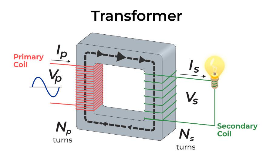
Transformer
- The transformer primary winding produces an alternating flux, known as the mutual flux, when an alternating voltage is applied, in accordance with the mutual inductance principle.
According to Faraday's rule of electromagnetic induction, this alternating flux links the transformer primary and secondary windings magnetically and generates EMFs E1 in the primary winding and E2 in the secondary winding. The EMF (E1) is referred to as the primary EMF, while the EMF (E2) is the secondary EMF.
E_1=-N_1\dfrac{\text{d}\phi_m}{\text{d}t}
and
E_2=-N_2\dfrac{\text{d}\phi_m}{\text{d}t}
Dividing above equations, to obtain the ratio as:
\dfrac{E_1}{E_2}=\dfrac{N_1}{N_2}
- From the expression above, it is clear that the size of EMFs **E 1 and E 2is dependent on the number of turns in the transformer primary and secondary windings, respectively. If N 2 > N 1 , then **E 2 > E 1, and the transformer will be a step-up transformer; if **N 2 < N 1 , then E 2 < E 1, and the transformer will be a step-down transformer.
- If a load is now connected across the secondary winding, the load current **I 2 will flow through the load as a result of the EMF **E 2 . As a result, a transformer makes it possible to transfer electricity with a change in voltage level from one electric circuit to another.
Parts of a Transformer
**A transformer majorly consists of three parts:
1. Core:
- The transformer core serves as a support for the winding. Additionally, it offers a magnetic flux flow channel with minimal resistance. As seen in the image, the winding is looped around the core. To cut down on losses in a transformer, it has a laminated soft iron core.
- Core composition is determined by variables including operational voltage, current, and power, among others. The core diameter is negatively correlated with iron losses and directly correlated with copper losses.
2. Windings:
- The copper wires that are wound over the transformer core are known as windings. Copper cables are used because Copper's high conductivity reduces transformer loss because resistance to current flow lowers as conductivity rises. And copper's high degree of ductility makes it possible to produce incredibly thin wires out of it.
- The two basic types of windings are. windings for the primary and secondary coils. The primary winding is the group of winding turns that receive supply current. The number of winding turns from which output is derived is known as secondary winding. Insulation coating agents are used to insulate the primary and secondary windings from one another.
3. Insulation Agents:
- Transformer require insulation to keep the windings apart and prevent short circuits. This makes mutual induction easier. Transformer stability and durability are influenced by insulation agents.
- In a transformer, the following are employed as insulating mediums: Insulating fluid, tape, Paper, and Lamination made of wood.
**4. Tank:
A transformer main tank serves two purposes:
- The core and the windings are protected from the elements, such as rain and dust.
- It functions as an oil container as well as a support for all other transformer attachments.
**5. Transformer Oil:
- The majority of the huge transformer are submerged in oil.
- The transformer oil adds insulation between the conductors, improves heat dissipation from the coils, and has fault-detecting capabilities. Transformer oil is typically made of hydrocarbon mineral oil.
**6. Oil Conservators:
- The oil conservator is situated above the transformer tank and bushings. Some transformer oil conservators contain a rubber bladder. When a transformer is loaded, the ambient temperature rises, causing the amount of oil inside the transformer to increase.
- The transformer conservator tank has enough room for the increased transformer oil. It also serves as a reservoir for oil that is used to insulate buildings.
**7. Breather:
- All oil-immersed transformer with conservator tank includes it.
- It aids in the protection of the oil against moisture.
**8. Radiators and Fans:
- The majority of the power lost in the transformer is dissipated as heat.
- Radiators and fans aid in the dissipation of heat generated by the transformer and provide protection against failure. The majority of dry transformer are cooled by natural air.
Ideal Transformer
An ideal transformer is a purely theoretical transformer that has no losses at all, including no core losses, copper losses, or other transformer losses. This transformer is thought to be 100% efficient.
- The windings of the transformer are assumed to be entirely inductive, and the core of the transformer is assumed to be loss-free when creating the ideal transformer model.
- Additionally, the transformer has no leakage reactance (reactance is the opposition to the flow of current from the circuit element due to its inductance and capacitance).
- This indicates that the transformer primary and secondary windings are connected to the core of the transformer at 100% flux. However, every winding must have some inductive resistance that results in voltage drop and **I 2 R loss.
- In a model of an ideal transformer, the windings are assumed to be perfect (totally inductive), which means that their resistance is zero.
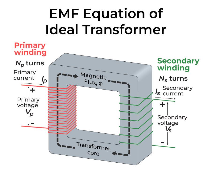
EMF Equation of Ideal Transformer
- Let '**N p ' is the main winding's number of turns, whereas 'N s **'**is the secondary winding's number of turns. When an AC voltage is given to the transformer main coil, the current generated creates an alternating magnetic flux that connects the secondary coil and generates an emf.
- The number of turns in the secondary coil determines the value of this emf. Consider an ideal (lossless) transformer with zero primary coil resistance (no voltage drop across coil) and all flux in the core connecting both primary and secondary windings.
- When the voltage '**V p ' is delivered to the primary coil, let be the flux linkage in each turn in the core at time '**t 'owing to the current in the primary coil.
EMF Equation of Ideal Transformer
The induced emf or voltage (εs) in the secondary with Ns turns is then calculated.
εs = –Ns x dϕ/dt ......(1)
In addition, the alternating flux generates a reverse emf in the main. This is it.
εp = –Np x dϕ/dt ......(2)
And for an ideal transformer, εp=Vp
By approximation, if the secondary is an open circuit or the current drawn from it is modest, εs=Vs.
The voltage across the secondary coil is Vs. As a result, Equations (1) and (2) may be written as
Vs = –Ns x dϕ/dt ......(3)
Vp = –Np x dϕ/dt ......(4)
From Equations (3) and (4), we have
**V s / V p **= N s / N p ......(5)
The above equation is known as Transformer Equation or**Transformer Formula.
**The following three assumptions are used to get the previous relationship:
- The primary and secondary coils' electrical resistances are insignificant.
- The flux connectivity to both the primary and secondary coils is the same, or very few fluxes escape from the core.
- The secondary current is insignificant.
Turn Ratio
Turn Ratio is a measure to determine whether the secondary coil of a transformer has more or lesser windings than the primary. The number of windings on a primary coil is equal to "**Np," while the number of windings on a secondary coil is ****"Ns,"** representing the number of turns.
The power input and output will be equal if the transformer is perfect or 100 percent efficient (no energy losses).
ipVp = isVs ......(6)
Combining Equations (5) and (6), we have
**i p /i s **= V s /V p = N s /N p =K
The turn ratio, K, is defined in the preceding equation. If the secondary coil has more turns than the primary coil, this is the case ****(N** s >N p ), and the voltage is stepped up ****(V** s >V p). A step-up transformer is a name for this sort of setup. A step-down transformer is one in which the secondary coil has fewer turns than the primary coil (N s <N p ).
**Efficiency of Transformer
The efficiency of a transformer is also known as **commercial efficiency. It is represented by the letter **‘η’. The efficiency of a Transformer is described as the ratio of output (in W or kW) to input ****(in W or kW).**
**Hence, the efficiency of transformer may be expressed as follows:
**Efficiency (η) = (Power Output / Power Input)
The above equation can be used for an ideal transformer in which there are no transformer losses and all input energy is transferred to the output. As a result, the following equation is mostly used if transformer wastes are taken into account and the efficiency of the transformer is evaluated across the practical states.
**Efficiency = ((Power O/P) / (Power O/P + Losses)) × 100%
or
**Efficiency = (Power i/p – Losses) / Power i/p × 100 = 1− (Losses/ i/p Power) × 100
Energy Losses in a Transformer
**We used an ideal transformer in the previous equations (without any energy losses). However, some energy losses do occur in actual transformer for the following reasons:
- **Flux Leakage: Because some flux leaks from the core, not all flux generated by the primary coil make it to the secondary coil. This occurs as a result of the core's inadequate design or the presence of air holes in the core. It is possible to lower it by wrapping the primary and secondary coils over each other. It can also be lowered if the core is well-designed.
- **Windings Resistance: Because the wire used for the windings has some electrical resistance, energy is wasted as a result of the heat generated in the windings. These are mitigated in high current, low voltage windings by utilizing thick wire with a high conductive substance.
- **Eddy Currents: The alternating magnetic flux creates eddy currents in the iron core, resulting in energy losses through heating. By using a laminated core, the impact is decreased.
- **Hysteresis Loss: In each AC cycle, the alternating magnetic field reverses the magnetization of the core. The loss of energy in the core occurs as heat owing to hysteresis loss, which is minimized by employing a magnetic material with a low hysteresis loss.
Application of Transformer
**The following are some of the most common uses for transformer:
- Increasing or reducing the voltage level in an AC circuit to ensure the correct operation of the circuit's various electrical components.
- It stops DC from flowing from one circuit to another.
- It separates two separate electric circuits.
- Before transmission and distribution can take place, the voltage level at the electric power plant must be increased.
Solved Examples - Transformer
**Example 1: A transformer primary winding is powered by a 120 V ac source. If the turn ratio is 10, what does the secondary voltage equal?
Given that, the turn ratio, N2/N1 = 10
And thevoltage across the primary coil, V1 = 120 V
Now, according to the transformer;'s equation:
V2/V1 = N2/N1
Substituting the given values,
V2/120 = 10
V2 = **1200 V
**Example 2: A transformer has 1000 turns in the primary coil, and 8 A current flows through it. When the input power is 10 kW, and the output is 1000 V. Determine the number of turns in the secondary coil.
Consider the case of an Ideal Transforemer,
Given that, Pin = Pout = 1000 W
But, Pout = VSIS
Now, the current through the secondary circuit is,
IS = Pout / VS =10000 / 1000 = 10 A
Therefore, the turns ratio of transformer is given by,
IP / IS = NS / NP
NS = (IP / IS) NP
= (8/10) × 1000
= 800 turns.
**Example 3: The number of turns in the secondary coil of a 22 KVA, 2200V/220V single-phase transformer is 50, then find the number of primary turns. Neglect all kinds of losses in the transformer.
The value of the turns ratio is
Vp/Vs = 2200/220
=10 = K
Number of primary turns
The value of the primary turns can be determined as:-
Np/Ns=K
Np/50=10
Np = **500
**Example 4: Determine the primary current drawn in the transformer when the efficiency of the transformer provided is 75% and works on 100 V, 5 kVA and secondary voltage is 200 V.
Given that, The kVA rating of transformer= 5 kVA
Primary voltage, V1 = 100 V
Secondary voltage, V2 = 200 V
Therefore, the Primary current I1 is given by,
I1= S / V1
= 5 kVA / 100
= **50 A
**Also Check: