Sequential circuits (original) (raw)
Consider the data given in Q50 question. If all the flip-flops were reset to 0 at power on, what is the total number of distinct outputs (states) represented by PQR generated by the counter?
Consider the following circuit involving three D-type flip-flops used in a certain type of counter configuration.
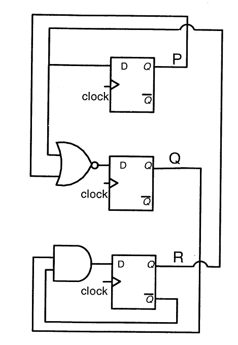
If at some instance prior to the occurrence of the clock edge, P, Q and R have a value 0, 1 and 0 respectively, what shall be the value of PQR after the clock edge?
In the sequential circuit shown below,if the initial value of the output Q1Q0 is 00,what are the next four values of Q1Q0?
A D flip-flop is to be connected to an 8085 microprocessor chip as a 1-bit output port with a port address of FF hex. Data bit D3 should be involved in the data transfer from CPU to the flip-flop. The flip-flop should be cleared on power ON.
- a. Using only one NAND gate (fan in of 10), one NOT gate and one D flip-flop. Draw the required interface logic circuit (only the relevant signals should be shown).
- b. Write a program to generate a square wave on the output of the flip-flop. ON and OFF periods of the square wave should be 7 bus cycles each.
What does the following logic diagram represent? 
Design a synchronous counter to go through the following states: 1, 4, 2, 3, 1, 4, 2, 3, 1, 4,...........
Consider the synchronous sequential circuit in the below figure a) Draw a state diagram, which is implemented by the circuit. Use the following names for the states corresponding to the values of flip-flops as given below.
 b) Given that the initial state of the circuit is S4, identify the set of states, which are not reachable.
Consider following counters: Counter-1:  Counter-2:
  Which of the following option is correct?
- Counter-1 is a three-bit "counter" which counts 0, 1, 2, 4, 5, 7, 0, ... . and Counter-2 is a three-bit "counter" which counts 0, 3, 6, 1, 4, 7, 2, 5, 0, 3, ... .
- Counter-1 is a three-bit "counter" which counts 0, 2, 6, 1, 4, 7, 2, 5, 0, 2, ... . and Counter-2 is a three-bit "counter" which counts 0, 1, 2, 4, 5, 7, 0, ... .
- Counter-1 is a three-bit "counter" which counts 0, 3, 6, 1, 4, 7, 2, 5, 0, 3, ... . and Counter-2 is a three-bit "counter" which counts 0, 1, 2, 4, 5, 7, 0, ... .
- Counter-1 is a three-bit "counter" which counts 0, 3, 6, 1, 4, 7, 2, 5, 0, 3, ... . and Counter-2 is a three-bit "counter" which counts 0, 1, 2, 3, 5, 6, 0, ... .
Consider the following statements regarding counters:
S1 : The Hamming distance of an Overbeck counter is 1 and the Hamming distance of a Johnson counter is 2. S2 : Only output sequence 0, 8, 12, 14, 15, 7, 3, 1, 0, ... is possible in Overbeck counter but not output sequence 2, 1, 8, 4, 2, 1, ... S3 : A binary counter can represent 2^N states, where N is the number of bits in the code, whereas an Overbeck counter can represent only N states and a Johnson counter can represent only 2N states.
- Only S1, S2 are false and S3 is true
- Only S2, S3 are false and S1 is true
- Only S1, S3 are false and S2 is true
- All S1, S2, and S3 are true
Consider the sequential circuit shown in the figure, where both flip-flops used are positive edge-triggered D flip-flops.
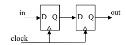
The number of states in the state transition diagram of this circuit that have a transition back to the same state on some value of "in" is ______ . **Note - This was Numerical Type question.
There are 46 questions to complete.
Take a part in the ongoing discussion