Control Flow Graph (CFG) Software Engineering (original) (raw)
Last Updated : 11 Jul, 2025
A **Control Flow Graph (CFG) is the graphical representation of control flow or computation during the execution of programs or applications. Control flow graphs are mostly used in static analysis as well as compiler applications, as they can accurately represent the flow inside a program unit. The control flow graph was originally developed by _Frances E. Allen.
Characteristics of Control Flow Graph
- The control flow graph is process-oriented.
- The control flow graph shows all the paths that can be traversed during a program execution.
- A control flow graph is a directed graph.
- Edges in CFG portray control flow paths and the nodes in CFG portray basic blocks.
There exist 2 designated blocks in the Control Flow Graph:
- **Entry Block: The entry block allows the control to enter into the control flow graph.
- **Exit Block: Control flow leaves through the exit block.
Hence, the control flow graph comprises all the building blocks involved in a flow diagram such as the start node, end node, and flows between the nodes.
General Control Flow Graphs
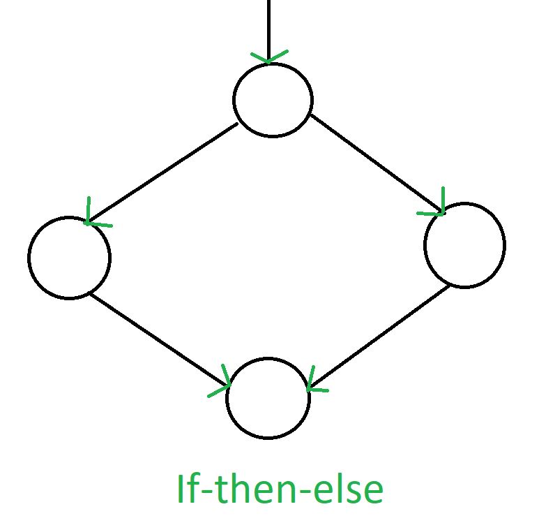
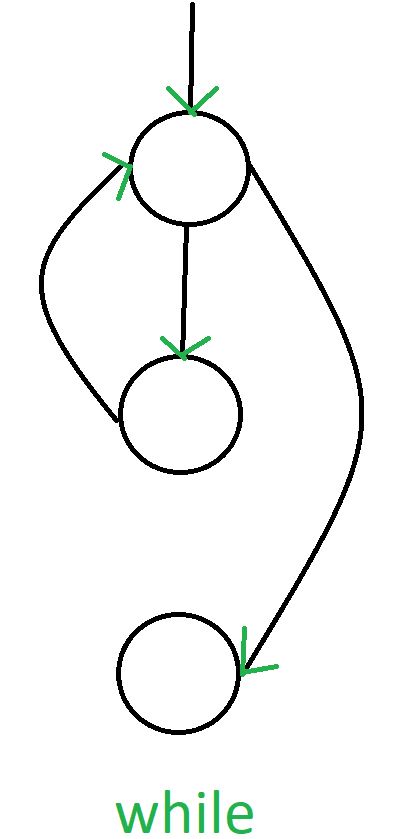
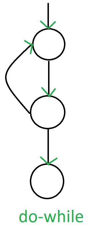
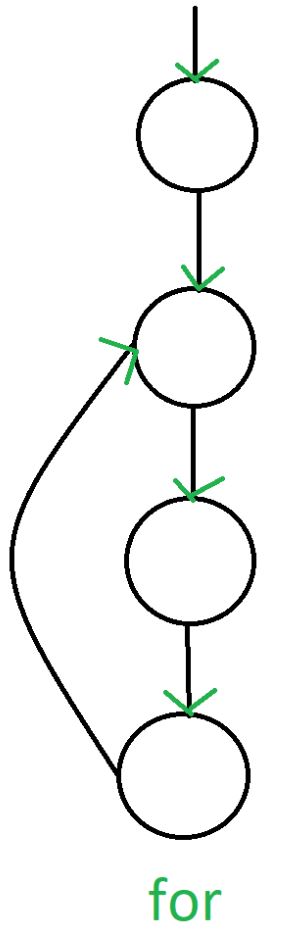
Control Flow Graph is represented differently for all statements and loops. The following images describe it:
1. If-else
2. **While
3. **do-while
4. **for
Example
if A = 10 then
if B > C
A = B
else A = C
endif
endif
print A, B, C
Flowchart of above example will be:
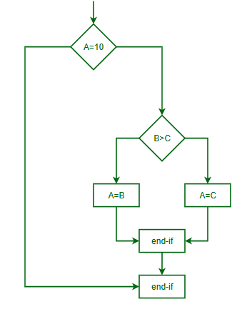
control flow graph
Control Flow Graph of above example will be:
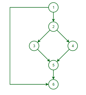
control flow graph
Advantage of CFG
- **Visualizes program flow: Easy to see how a program runs.
- **Helps find errors: Detects unreachable code or infinite loops.
- **Useful for optimization: Improves program performance.
- **Aids testing: Ensures all parts of the code are tested.
Disadvanatges of CFG
- **Complex for big programs: Hard to understand.
- **No unpredictable behavior: Can’t show unclear paths.
- **No data info: Only shows program flow.
- **Not scalable: Becomes messy for large projects.
Conclusion
Control Flow Graph (CFG) is a helpful tool to understand how a program works. It makes it easier to find errors, improve performance, and ensure thorough testing. While it can get complex for large programs, it’s still a valuable way to analyze and optimize code effectively.