Unified Modeling Language (UML) Diagrams (original) (raw)
Unified Modeling Language (UML) is a general-purpose modeling language. The main aim of UML is to define a standard way to visualize the way a system has been designed. It is quite similar to blueprints used in other fields of engineering. UML is not a programming language, it is rather a visual language.
-Diagrams.webp)
Table of Content
- What is UML?
- Why do we need UML?
- Types of UML Diagrams
- Structural UML Diagrams
- Behavioral UML Diagrams
- Object-Oriented Concepts Used in UML Diagrams
- Tools for creating UML Diagrams
- Steps to create UML Diagrams
- UML Diagrams Best Practices
- When to Use UML Diagrams
- UML and Agile Development
- Common Challenges in UML Modeling
- Benefits of Using UML Diagrams
1. What is UML?
Unified Modeling Language (UML) is a standardized visual modeling language that is a versatile, flexible, and user-friendly method for visualizing a system's design. Software system artifacts can be specified, visualized, built, and documented with the use of UML.
- We use UML diagrams to show thebehavior and structure of a system.
- UML helps software engineers, businessmen, and system architects with modeling, design, and analysis.
The International Organization for Standardization (ISO) published UML as an approved standard in 2005. UML has been revised over the years and is reviewed periodically.
**2. Why do we need UML?
We need UML (Unified Modeling Language) to visually represent and communicate complex system designs, facilitating better understanding and collaboration among stakeholders. Below is why we need UML:
- Complex applications need collaboration and planning from multiple teams and hence require a clear and concise way to communicate amongst them.
- Businessmen do not understand code. So UML becomes essential to communicate with non-programmers about essential requirements, functionalities, and processes of the system.
- A lot of time is saved down the line when teams can visualize processes, user interactions, and the static structure of the system.
3. Types of UML Diagrams
UML is linked with object-oriented design and analysis. UML makes use of elements and forms associations between them to form diagrams. Diagrams in UML can be broadly classified as:

4. Structural UML Diagrams
Structural UML diagrams are visual representations that depict the static aspects of a system, including its classes, objects, components, and their relationships, providing a clear view of the system's architecture. Structural UML diagrams include the following types:
**4.1. Class Diagram
The most widely use UML diagram is the class diagram. It is the building block of all object oriented software systems. We use class diagrams to depict the static structure of a system by showing system's classes, their methods and attributes. Class diagrams also help us identify relationship between different classes or objects.
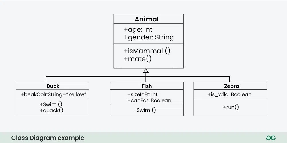
Class Diagram
**4.2. Composite Structure Diagram
We use composite structure diagrams to represent the internal structure of a class and its interaction points with other parts of the system.
- A composite structure diagram represents relationship between parts and their configuration which determine how the classifier (class, a component, or a deployment node) behaves.
- They represent internal structure of a structured classifier making the use of parts, ports, and connectors.
- We can also model collaborations using composite structure diagrams.
- They are similar to class diagrams except they represent individual parts in detail as compared to the entire class.
**4.3. Object Diagram
An Object Diagram can be referred to as a screenshot of the instances in a system and the relationship that exists between them. Since object diagrams depict behaviour when objects have been instantiated, we are able to study the behaviour of the system at a particular instant.
- An object diagram is similar to a class diagram except it shows the instances of classes in the system.
- We depict actual classifiers and their relationships making the use of class diagrams.
- On the other hand, an Object Diagram represents specific instances of classes and relationships between them at a point of time.
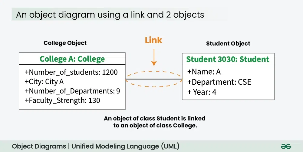
Object Diagram
**4.4. **Component Diagram
Component diagrams are used to represent how the physical components in a system have been organized. We use them for modelling implementation details.
- Component Diagrams depict the structural relationship between software system elements and help us in understanding if functional requirements have been covered by planned development.
- Component Diagrams become essential to use when we design and build complex systems.
- Interfaces are used by components of the system to communicate with each other.
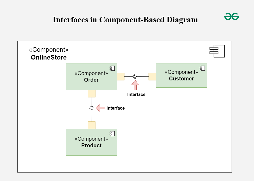
Component Diagram
**4.5. Deployment Diagram
Deployment Diagrams are used to represent system hardware and its software. It tells us what hardware components exist and what software components run on them.
- We illustrate system architecture as distribution of software artifacts over distributed targets.
- An artifact is the information that is generated by system software.
- They are primarily used when a software is being used, distributed or deployed over multiple machines with different configurations.
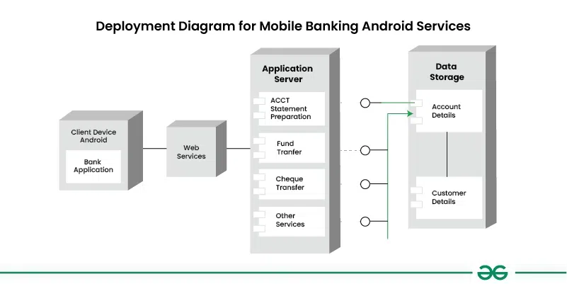
Deployement Diagram
**4.6. Package Diagram
We use Package Diagrams to depict how packages and their elements have been organized. A package diagram simply shows us the dependencies between different packages and internal composition of packages.
- Packages help us to organise UML diagrams into meaningful groups and make the diagram easy to understand.
- They are primarily used to organise class and use case diagrams.
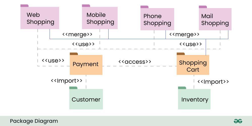
Package Diagram
5. Behavioral UML Diagrams
Behavioral UML diagrams are visual representations that depict the dynamic aspects of a system, illustrating how objects interact and behave over time in response to events.
**5.1. State Machine Diagrams
A state diagram is used to represent the condition of the system or part of the system at finite instances of time. It’s a behavioral diagram and it represents the behavior using finite state transitions.
- State diagrams are also referred to as State machines and State-chart Diagrams
- These terms are often used interchangeably. So simply, a state diagram is used to model the dynamic behavior of a class in response to time and changing external stimuli.
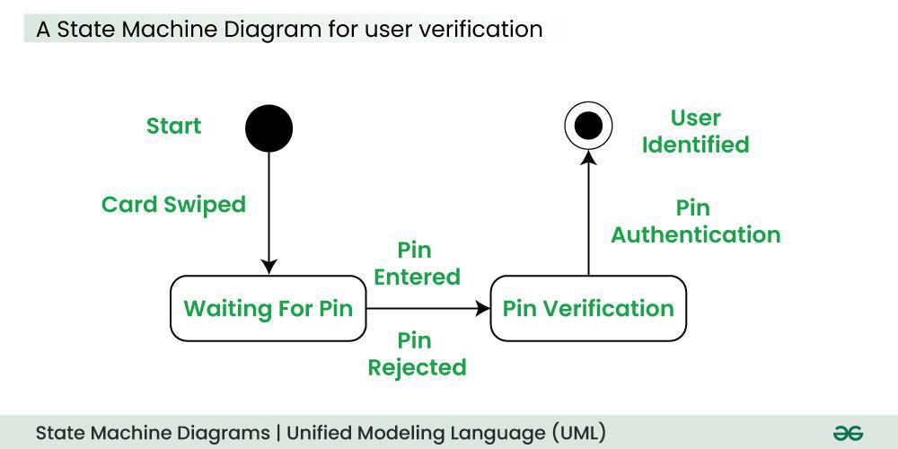
State Machine Diagram
**5.2. Activity Diagrams
We use Activity Diagrams to illustrate the flow of control in a system. We can also use an activity diagram to refer to the steps involved in the execution of a use case.
- We model sequential and concurrent activities using activity diagrams. So, we basically depict workflows visually using an activity diagram.
- An activity diagram focuses on condition of flow and the sequence in which it happens.
- We describe or depict what causes a particular event using an activity diagram.
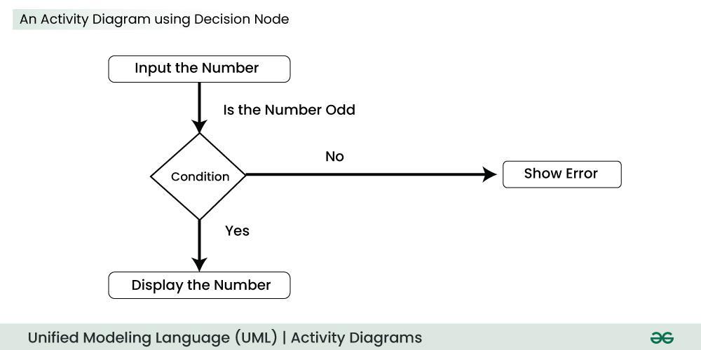
Activity Diagram
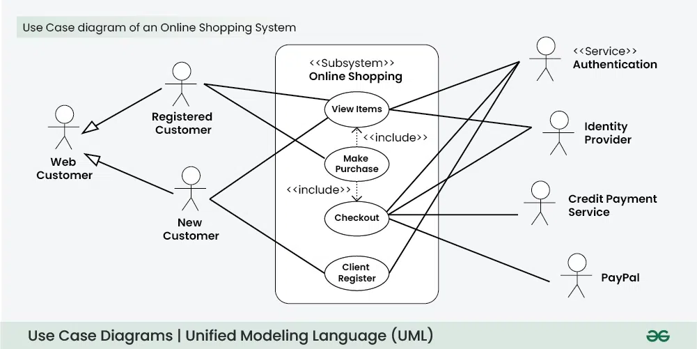
**5.3. Use Case Diagrams
Use Case Diagrams are used to depict the functionality of a system or a part of a system. They are widely used to illustrate the functional requirements of the system and its interaction with external agents(actors).
- A use case is basically a diagram representing different scenarios where the system can be used.
- A use case diagram gives us a high level view of what the system or a part of the system does without going into implementation details. '
**5.4. Sequence Diagram
A sequence diagram simply depicts interaction between objects in a sequential order i.e. the order in which these interactions take place.
- We can also use the terms event diagrams or event scenarios to refer to a sequence diagram.
- Sequence diagrams describe how and in what order the objects in a system function.
- These diagrams are widely used by businessmen and software developers to document and understand requirements for new and existing systems.
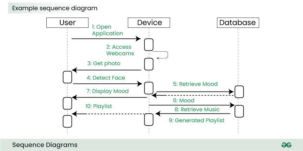
Sequence Diagram
**5.5. Communication Diagram
A Communication Diagram (known as Collaboration Diagram in UML 1.x) is used to show sequenced messages exchanged between objects.
- A communication diagram focuses primarily on objects and their relationships.
- We can represent similar information using Sequence diagrams, however communication diagrams represent objects and links in a free form.

Communication Diagram
**5.6. Timing Diagram
Timing Diagram are a special form of Sequence diagrams which are used to depict the behavior of objects over a time frame. We use them to show time and duration constraints which govern changes in states and behavior of objects.
**5.7. Interaction Overview Diagram
An Interaction Overview Diagram (IOD) is a type of UML (Unified Modeling Language) diagram that illustrates the flow of interactions between various elements in a system or process. It provides a high-level overview of how interactions occur, including the sequence of actions, decisions, and interactions between different components or objects.
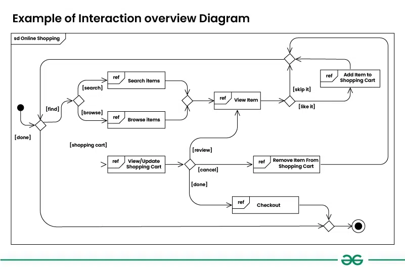
Interaction Overview Diagram
6. Object-Oriented Concepts Used in UML Diagrams
Examples of object-oriented concepts in UML diagrams include classes, objects, inheritance, abstraction, encapsulation, and polymorphism. These concepts improve modularity and clarity by offering an orderly way to show complex systems.
- **Class: An object's structure and behavior are defined by its class, which serves as a blueprint.
- **Objects: We may divide complex systems into smaller, more manageable components by using objects. Because of its modularity, we can concentrate on easily understood components and develop the system gradually.
- **Inheritance: Child classes can inherit the characteristics and functions of their parent classes.
- **Abstraction: The main characteristics of a system or object are highlighted in UML abstraction, while extraneous details are ignored. Stakeholder communication and understanding are improved by this simplification.
- **Encapsulation: Encapsulation is the process of integrating data and restricting external access in order to maintain the integrity of the data.
- **Polymorphism: Flexibility in their use is made possible by polymorphism, the capacity of functions or entities to take on multiple forms.
6.1. Additions in UML 2.0
- Software development methodologies like agile have been incorporated and scope of original UML specification has been broadened.
- Originally UML specified 9 diagrams. UML 2.x has increased the number of diagrams from 9 to 13. The four diagrams that were added are : timing diagram, communication diagram, interaction overview diagram and composite structure diagram. UML 2.x renamed statechart diagrams to state machine diagrams.
- UML 2.x added the ability to decompose software system into components and sub-components.
There are several tools available for creating Unified Modeling Language (UML) diagrams, which are commonly used in software development to visually represent system architecture, design, and implementation. Here are some popular UML diagram creating tools:
- Lucidchart: Lucidchart is a web-based diagramming tool that supports UML diagrams. It's user-friendly and collaborative, allowing multiple users to work on diagrams in real-time.
- Draw.io: Draw.io is a free, web-based diagramming tool that supports various diagram types, including UML. It integrates with various cloud storage services and can be used offline.
- Visual Paradigm: Visual Paradigm provides a comprehensive suite of tools for software development, including UML diagramming. It offers both online and desktop versions and supports a wide range of UML diagrams.
- StarUML: StarUML is an open-source UML modeling tool with a user-friendly interface. It supports the standard UML 2.x diagrams and allows users to customize and extend its functionality through plugins.
8. Steps to create UML Diagrams

Creating Unified Modeling Language (UML) diagrams involves a systematic process that typically includes the following steps:
- Step 1: Identify the Purpose:
- Decide on the objective for which the UML diagram is being made. Among the many applications for the many types of UML diagrams are requirements collection, system architecture development, and class relationship documentation.
- Step 2: Identify Elements and Relationships:
- Choose which crucial elements—classes, objects, use cases, etc.—should be included in the diagram, along with their relationships.
- Step 3: Select the Appropriate UML Diagram Type:
- Select the type of UML diagram that best suits your modeling requirements. Class diagrams, use case diagrams, sequence diagrams, activity diagrams, and more are examples of common forms.
- Step 4: Create a Rough Sketch:
- A basic sketch on paper or a whiteboard can be useful before utilizing a UML modeling tool. This can assist you in seeing how the elements are arranged and related to one another.
- Step 5: Choose a UML Modeling Tool:
- Choose a UML modeling tool based on your needs. Numerous offline and online applications are available with features for making and modifying UML diagrams.
- Step 6: Create the Diagram:
- Create a new project or diagram using the UML modeling tool of your choice. Start by adding components to the diagram, such as actors, classes, and use cases, and then link them together with the proper relationships, such as dependencies and associations.
- Step 7: Define Element Properties:
- Give each diagram element the appropriate qualities and attributes. Use case specifics, class characteristics and methods, and any other information unique to the diagram type may be included.
- Step 8: Add Annotations and Comments:
- By using annotations, remarks, and clarifying notes, you can improve the diagram's readability.
- Step 9: Validate and Review:
- Check the diagram for completeness and accuracy. Make that the elements, limitations, and linkages appropriately depict the system or process that is intended.
- Step 10: Refine and Iterate:
- Refine the diagram based on feedback and additional insights. UML diagrams are often created iteratively as the understanding of the system evolves.
Note: Remember that the specific steps may vary based on the UML diagram type and the tool you are using.
9. UML Diagrams Best Practices
System design can be visually represented and documented with the help of the Unified Modeling Language (UML). Best practices must be followed in order to produce UML diagrams that are both useful and significant. UML best practices include the following:
- **Understand the Audience: Consider who will view your UML diagrams as you create them. Whether your audience consists of developers, architects, or stakeholders, make sure the type and degree of detail of the diagram meet their needs.
- **Keep Diagrams Simple and Focused: Make sure your diagrams are as simple as possible. Each one need to draw attention to a certain aspect of the system or illustrate a particular link.
- **Use Consistent Naming Conventions: Use clear and consistent names for classes, objects, attributes, and methods. Good naming helps everyone understand the diagrams better.
- **Follow Standard UML Notations: Stick to standard UML symbols and notations. This consistency makes it easier for anyone familiar with UML to understand your diagrams.
- **Keep Relationships Explicit: Clearly define and label how different elements are connected. Use the right arrows and notations to show the nature of relationships between classes, objects, or use cases.
10. When to Use UML Diagrams
Use UML Diagrams:
- When a system's general structure needs to be represented, UML diagrams can help make it clearer how various parts work together, which facilitates idea sharing between stakeholders.
- When collecting and recording system requirements, UML diagrams, such as use case diagrams, can help you clearly grasp user demands by showing how users will interact with the system.
- If you're involved in database design, class diagrams are great for illustrating the relationships among various data entities, ensuring your data model is well-organized.
- When working with team members or clients, UML diagrams act as a shared language that connects technical and non-technical stakeholders, improving overall understanding and alignment.
11. UML and Agile Development
Although Agile development and UML (Unified Modeling Language) are two distinct approaches to software development, they can work well together. This is how they are related:
11.1. UML in Agile Development
- **Visual Communication: System behavior and design are demonstrated with the help of UML diagrams. Agile emphasizes the need of clear communication, and these diagrams help all parties involved—team members, stakeholders, and even non-technical individuals—understand what is happening.
- **Capturing User Stories: Use case diagrams in UML can help capture user stories, showing how users will interact with the system. This helps everyone understand the user’s perspective better.
- **Building in Steps: Agile development is all about working in small steps, and UML can adapt to this by allowing models to be created and updated as the project evolves.
- **Simplifying Requirements: Techniques like user story mapping can go hand-in-hand with UML, making it easier to visualize what needs to be done without overwhelming documentation.
11.2. Balancing Modeling with Agility
- **Smart Modeling: Use UML as much as needed to help with communication, focusing on delivering useful software rather than getting bogged down in paperwork.
- **Empowering the Team: Give the team the freedom to decide how much modeling is necessary. They should feel comfortable using UML without feeling pressured to create too many diagrams
12. Common Challenges in UML Modeling
Below are the common challenges in UML Modeling:
- Accurately representing complex system requirements can be difficult, leading to either oversimplification or overwhelming detail.
- Team members may interpret the model differently, resulting in inconsistencies and misunderstandings about its purpose.
- Keeping UML diagrams current as the system evolves can be time-consuming, risking outdated representations if not managed effectively.
- Agile promotes teamwork, but sometimes UML diagrams are complicated and only a few people understand them. It can be hard to make sure everyone can contribute to and use the diagrams effectively.
13. Benefits of Using UML Diagrams
Below are the benefits of using UML Diagrams:
- Developers and stakeholders may communicate using a single visual language thanks to UML's standardized approach to system model representation.
- Developers, designers, testers, and business users are just a few of the stakeholders with whom UML diagrams may effectively communicate.
- UML diagrams make it easier to see the linkages, processes, and parts of a system.
- One useful tool for documentation is a UML diagram. They offer an ordered and systematic method for recording a system's behavior, architecture, and design, among other elements.