Microscale Assembly Directed by Liquid-based Template (original) (raw)
. Author manuscript; available in PMC: 2015 Sep 10.
Published in final edited form as: Adv Mater. 2014 Jun 23;26(34):5936–5941. doi: 10.1002/adma.201402079
Abstract
Liquid surface established by standing waves is used as a dynamically reconfigurable template to assemble microscale materials into ordered, symmetric structures in a scalable and parallel manner. We illustrate broad applicability of this technology by assembling diverse materials from soft matter, rigid bodies, individual cells, cell spheroids and cell-seeded microcarrier beads.
Keywords: bottom-up, liquid-based template, directed assembly, cell assembly, microscale materials, cell spheroids, microscale hydrogels, tissue engineering, biomanufacturing, neural engineering, Faraday waves
Spontaneous emergence of ordered and complex structures from simple building units is a ubiquitous phenomenon in nature in a wide range of the scales [1,2]. For example, water molecules crystallize into snowflakes, nucleotides self-assemble into DNAs, and sands pile into ripple or stripe patterns in desert. This natural creation mode represents a smarter strategy and a higher efficiency than many human approaches that build an architecture piece by piece. Recently, assembly of microscale materials has drawn increasing attention due to great demands in engineering architectures/systems in the fields including bottom-up tissue engineering [3], microelectromechanical systems [4] and microphotonics [5]. Of particular interest is tissue engineering, where organization of cells and cell microcarriers into repeating units with well-defined 3D architectures that mimic native tissues is significant for the resulting tissue-specific functions [6]. Previous microscale technologies have their own unique advantages in creating various structures from microscale materials. However, these existing technologies have limitations such as unaffordable time budgets for assembling large number of building units (e.g., bioprinting [7], micro-robotic assembly [8]), incapability for reconfiguring final structure after the mold is created (e.g., micromolding [9], microscale templated assembly based on solid molds [10,11]), limited types or complexity in resulting structures/geometrics (e.g., magnetic assembly [10,12], electrostatic assembly [13], capillary assembly [14], molecular recognition [15]).
Here, we report a versatile bottom-up method that enables efficient generation of diverse structures from microscale materials in a reconfigurable and biocompatible way. We explore the topography of liquid surface established by standing waves serves as a template for directed assembly of large number (~106) of microscale materials into diverse sets of ordered, symmetric structures. This liquid-based template can be dynamically reconfigured in a few seconds (< 5 s), and the assembly on the template can be achieved in a scalable and parallel manner. We illustrate broad applicability of this approach by assembling diverse materials sized from 10 μm to 2 mm including soft matter, rigid bodies, mammalian cells, cell spheroids and cell-seeded microcarrier beads into structures ranging in area from 100 mm2 to 10,000 mm2. In addition, we show that the assembled structures can be immobilized by chemical- and photo-crosslinking for the subsequent applications.
Results and Discussion
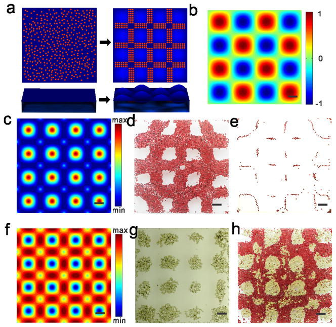
Microscale materials suspend on a static fluid surface due to the balance of surface tension force, buoyant force and gravity force. After generating standing waves as a template, these microscale materials are driven by drift energy gradient and cover the liquid surface from the region with the lowest drift energy to the region with high drift energy (Figure 1a). The drift energy, U, experienced by a floater with a radius R in an applied standing wave can be simply described as follows, assuming no boundary effects on the standing waves,
Figure 1. Principle demonstration of liquid-based templated assembly.
a, Schematics of assembly based on liquid-based template. b, Top down of the standing waves simulated according to equation (S2) in the supplementary information. Color bar indicates wave amplitude. c, Numerical simulation of drift energy for 200 μm polystyrene divinylbenzene beads on the standing waves based on equation (1). d–e, Assembly of polystyrene divinylbenzene beads on the nodal regions of standing waves with different coverage rate of beads on the air–liquid surface (d, 53% e, 2.5%). f, Numerical simulation of drift energy for 200 μm copper-zinc powder on the standing waves based on Equation (1). g, Assembly of copper-zinc powder on the antinodes of the standing waves. h, Assembly of complementary pattern by using copper-zinc powder (yellow regions) and polystyrene divinylbenzene beads (red regions). Chamber dimensions are 20 mm × 20 mm × 1.5 mm for all the experiments and simulations. Scale bars, 2 mm.
| U=[43πR3ρpar-πρliqRδ2+πρliqδ33]ω24∣ζ∣2+3π2μδαω∣ζ90°∣ | (1) |
|---|
where R is the floater radius, ρpar is the floater density, ρliq is the liquid density, δ is the submerged length of the floater in the liquid which is a function of R, ρpar, ρliq and the contact angle of the floater θ, ω is the angular frequency of the standing waves, ζ is the deformation of the fluid surface, μ is the dynamic viscosity of the liquid, α is the driving acceleration, and _ζ_90° is the deformation with 90° phase shift in x and y directions (Supplementary Text 1). Briefly, distribution of the drift energy is sensitive to contact angle and density ratio of the floater to fluid and is not sensitive to floater size and shape. Small contact angle and low density normally result in regions with the lowest drift energy on nodes of standing waves, while large contact angle and high density result in regions with the lowest drift energy on antinodes of standing waves. Lateral capillary forces also take effect on the local arrangement of floaters when floaters are near each other. These capillary forces don’t contribute to formation of the resulting global structure and thus are not included in the theoretical model.
Particularly, for polystyrene divinylbenzene beads in the standing waves as illustrated in Figure 1b, the lowest drift energy exists on nodal region (Figure 1c), resulting in nodal patterns with different coverage rates (Figure 1d–e). For copper-zinc powder in the same standing waves, the lowest drift energy exists on antinode region (Figure 1f), resulting in antinode pattern (Figure 1g). By introducing two types of microscale materials with complementary distributions of drift energy, complementary pattern of two types of materials can be achieved (Figure 1h).
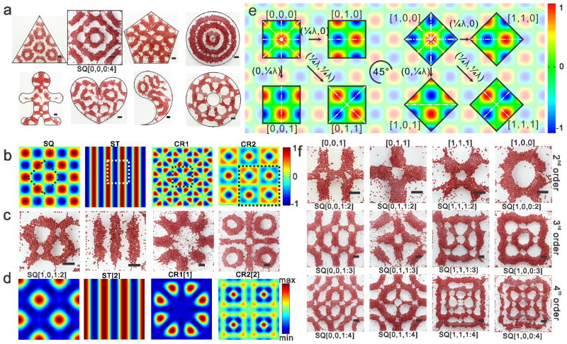
We obtain highly diverse sets of standing waves as liquid-based templates for assembling microscale materials. The diversity of the assembled structures originates from combinations of the chamber shape, waveform, and symmetric mode and harmonic order of the standing waves (Figure S1). We first perform assembly by exploiting the effect of chamber geometry on the standing wave formation (Figure 2a and S2). The assembly is achieved both in symmetric chambers and in the chambers without symmetry and even with pillars inside. Further, we investigate assembly in square chambers by tuning the vibrational parameters. The standing waves with the waveforms of squares, stripes and other crystalline structures are generated in experiments. The numerical simulation of each waveforms, an exemplified assembled structure and corresponding drift energy under each waveform is given in Figure 2b–d respectively (Supplementary Text 1). For each waveform type, there are several symmetric modes that are determined by the phase and direction of the standing waves constrained in the chamber. Taking the square waveform as an example, we find eight types of symmetric modes with one-, two- or four-fold reflection symmetries. The relationships between these modes are depicted by translating the standing waves by one-quarter wavelength in the _x_-axis and/or the _y_-axis direction in the constrained boundary or by rotating the standing waves about the center of the chamber by 45° (Figure 2e). For each type of symmetric mode, the standing waves can be generated from the low-order structure to the high-order structure by increasing vibrational frequency. The emergence order of these assembled structures over frequency is the same and repeatable for the chambers with the same shape but different sizes. The assembled structures generated by the square waveform are provided based on symmetric modes (columns) and harmonic orders (rows) in Figure 2f. These liquid-based templated assembly can be robustly controlled by the vibrational parameters and chamber geometry (Supplementary Text 2).
Figure 2.
Diversity of the structures created by liquid-based templated assembly. a, Chamber shape effect on the assembly. b, Numerical simulation of the waveforms generated in the square chamber. Square waveform (SQ), stripe waveform (ST) and crystalline waveforms (CR1 and CR2) were obtained using equation S2, S3 and S4 respectively. c–d, Typical assembled structure and corresponding drift energy (numerical simulation) under each waveforms. Each panel in c and d represents the dashed square in the corresponding panel of b. e, Principle demonstration of the symmetric modes within the square waveform. The color bar depicts the amplitude of the standing waves. Each code represents the symmetric modes. λ is the wavelength, and (λ/4, λ/4) indicates translation of the standing waves by λ/4 in both x-axis and y-axis directions. The symmetric axes are indicated with white dash-dotted lines. f, Harmonic order within each symmetric modes. All of the scale bars indicate 2 mm. Codes under the assembled structures are applied in the phase diagrams.
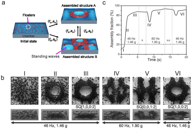
This liquid-based template demonstrates greater flexibility in reconfiguring its topography compared to the solid-based molding. The assembly can be reversibly transformed to any structures in the phase diagrams (Figure S3) in real time by resetting the vibrational parameters (Figure 3a), which suggests that the LBTA belongs to dynamic self-assembly [2,16]. A typical example is demonstrated in Figure 3b (Top-down view) and Video S1. Floaters are assembled into a ring-shaped structure under 1.46 g at 46 Hz. After the vibrational parameters are changed to 1.9 g at 60 Hz, the ring-shaped structure is transformed into an “H”-shaped structure. The assembled structure is restored to the ring shape after the vibration is set back to the original parameters. To characterize the fraction of floaters utilized in the assembly, we quantify the assembly fraction, which is defined as the ratio of the number of assembled floaters to the total number of floaters in the chamber. The study indicates that more than 80% of the floaters are assembled within 3 seconds (Figure 3c). From the side view (Figure 3b and Video S2), the floaters assemble as a monolayer on the nodal regions of the standing waves, leaving the antinodes uncovered. The antinodes of the standing wave alternate between crest and trough, which results in vertical oscillations in the assembled structure after the assembly process reaches a steady state. The change of the liquid topography results in a redistribution of the floaters in the chamber. We observe that most of the assembly is completed within 5 s regardless of vibrational parameters and coverage rate of floaters at the liquid surface (Supplementary Text 3 and Figure S4). Owing to the benefit of dynamic self-assembly, the structure created by the LBTA is robust to external perturbation [2,16]. The LBTA can spontaneously restore its original structure after being broken by external perturbation. For example, a ring-shaped structure is generated under 1.95 g at 44 Hz and is physically broken by stirring with a pipette tip. When the stirring is terminated, the suspended beads restore the ring shape within a few seconds (Video S3).
Figure 3. Dynamical reconfigurability of liquid-based templated assembly.
a, Schematic demonstration of dynamic reconfiguration of the assembled structures: (_f_A, _a_A) and (_f_B, _a_B) are vibrational frequencies and accelerations for the formation of structures A and B, respectively. By tuning the initial chamber with (_f_A, _a_A) and (_f_B, _a_B), assembly of the structures A and B from dispersed floaters can be performed, as well as the reversible transitions between the structures. b, Dynamic process of the assembly. I–VI show different stages of the assembly: I. before assembly; II. during assembly; III. formation of the ring-shaped structure; IV. intermediate state; V. formation of “H”-shaped structure; VI. restoration of the ring-shaped structure. All of the experiments were performed in10 mm × 10 mm × 1.5 mm chamber using beads with 200 μm in diameter. Scale bars, 2 mm. Note: The snapshots in top-down view and side view were recorded separately and approximately represent the events in the corresponding column. c, Time evolution of the assembly fraction during the assembly process. Vibration was applied at time zero. * Resetting vibrational parameters: the vibrational frequency was first increased from 46 Hz to 60 Hz, and the acceleration was then increased from 1.46 g to 1.9 g. ** Resetting vibrational parameters: the acceleration was first decreased from 1.9 g to 1.46 g, and the vibrational frequency was then decreased from 60 Hz to 46 Hz.
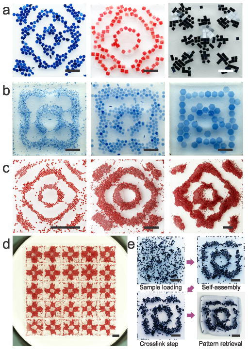
This liquid-based templated assembly demonstrate wide applicability for broad applications. First, the LBTA is applicable for floaters with various materials and varied sizes ranging from 10 μm to 2 mm. We demonstrate assembly of multiple materials, including methacrylated gelatin (GelMA) hydrogel units, polydimethylsiloxane (PDMS) blocks and silicon chiplets and copper powder, into nodal patterns, antinode patterns and complementary patterns (Figure 4a, 1g and 1h). We also show assembly of size-varied poly(ethylene glycol)(PEG) hydrogel units into the same structure (Figure 4b). The LBTA is applicable in the chamber with varying shapes (Figure 2a) and areas from 100 mm2 to 10,000 mm2 (Figure S5). In addition, LBTA allows scalable assembly of the same pattern with sized from 10 mm to 30 mm (Figure 4c) and parallel assembly of the same structure in a 5-by-5 chamber array (Figure 4d). Importantly, the assembled structures can be retrieved from the chamber via photo- (Figure 4e) or chemical crosslinking (Figure S6).
Figure 4. Broad applicability of liquid-based templated assembly.
a, Assembly of various materials. From left to right: GelMA hydrogel units (blue) and PDMS blocks (red) on nodal regions; silicon chiplets on antinodes. b, Assembly of size-varied materials. PEG hydrogel units with sizes of 0.5, 1, and 2 mm. c, Scalable assembly. Chamber sizes are 10, 20 and 30 mm respectively. Floater size is 200 μm for all. d, Parallel assembly in a 5-by-5 chamber array. Dimensions of each chamber are 10 mm × 10 mm × 1.5 mm. e, Photo crosslinking of the assembled structure. Once the hydrogels assembled, the crosslinking was performed to immobilize the hydrogels and the assembled pattern. Scale bars: 4 mm.
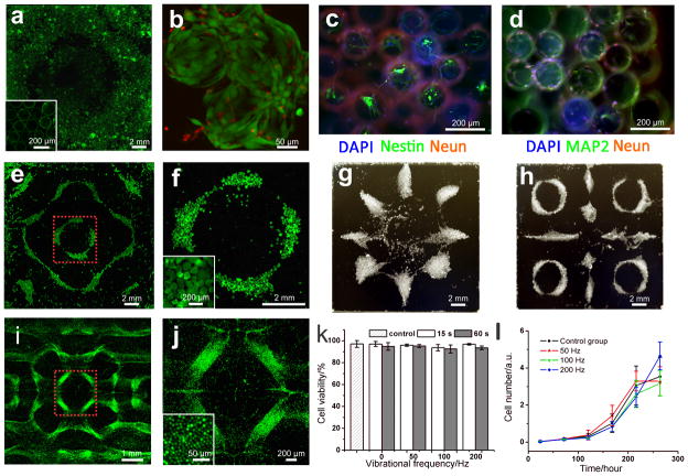
This liquid-based templated assembly also provides an alternative way for bottom-up tissue engineering. Polystyrene beads are used as microcarriers for cell assembly (Figure 5a, Video S4). Cell-seeded microcarrier beads can be assembled into various patterns as we demonstrated in Figure 2. After assembly, the formed motif of the cell-seeded beads are immobilized by chemical crosslinking with fibrinogen and thrombin. High cell viability is confirmed with live/dead assays after three-day culture of the system (Figure 5b). Assembly of neuron-seeded microcarrier beads into large-scale 3D neural structures is significant for developing in vitro models for understanding the wiring and mapping of neurons [17]. We assemble neuron-seeded beads and generated 3D neural strucutres positive for markers such as Nestin, NeuN and MAP-2 (Figure 5c–d and S7). Patterning cell spheroids into various shapes is of significance for tissue engineering due to the capability of spheroid’s fusion into micro-tissues [18]. Existing assembly methods are all based on the strategy of pick-and-place, which suffers from inefficiency. We demonstrate that LBTA simultaneous assembled ~103 cell spheroids (Figure 5e–h and S8). Additionally, scaffold-free cell assembly is a crucial challenge for tissue engineering due to small cell size and requirement for cytocompatibility. We demonstrate simultaneously assembly of a large number (~106) of cells into various patterns by LBTA (Figure 5i–j and S9). We evaluate cytocompatibility of LBTA by performing live/dead assays for cell viability and Alamar-Blue assays for cell proliferation. Within initial 24 h, cells experienced 15 and 60 s agitations at 50, 100 and 200 Hz don’t show significant difference in viability compared with control group (Figure 5k). 11-day cell culture further indicates that the cells exposed to the standing waves have no significant difference with control group in proliferation (Figure 5l). Comparing to previous reported directed assembly [10,12] or self-assembly approaches for tissue engineering [14,15,17,19], LBTA enables additional control over global shape of generated structure in a reconfigurable manner without any solid mould.
Figure 5. Liquid-based templated assembly for tissue engineering.
a–d, Assembly of cell-seeded microcarrier beads. a, Microcarrier beads with CFSE (Green) stained NIH 3T3 fibroblast cells after assembly and crosslinking. b, Live/dead assays on the cells seeded on the microcarrier beads, 3-day culture after chemical crosslinking. Green color indicates live cells (calcein-AM), red color indicates dead cells (ethidium homodimer-1). c–d, Formation of 3D neural structures on the assembled microcarrier beads after 14-day cell culture. e–h, Scaffold-free assembly of cells spheroids (mean size: 200 μm). f is magnified region in e, marked with red dashed lines. g–h, assembled structures from cell spheroids, bright field recorded by digital SLR camera. i–l, Scaffold-free assembly of fibroblast cells and cytocompatibility tests. i is magnified region in g, marked with red dashed lines. The cells were stained by cell tracker CFSE (Green). k, Cell viability test under assembly onset acceleration at various vibrational frequencies (n = 6); l, Cell proliferation test with Alamar blue. Cells experienced by 15-second agitations at 50, 100 and 200 Hz. The treated cells were seeded in a 64-well plate with a seeding density of 200 cells/well for 11-day cell culture. Data was presented as mean ± S.D. (n = 8).
We envision that LBTA opens a new paradigm for cost-effective and efficient manufacturing from microscale materials. Especially, it would be a useful biomanufacturing tool that enables various applications for bottom-up tissue engineering.
Supplementary Material
Supporting Information
Acknowledgments
We thank Drs. M.C. Demirel, S. Wang, H. Shafiee, I. Gözen, O. Tokel, O. Önen, F. Inci for comments on the manuscript; Dr. I.C. Ghiran, B. Erkmen, Harvard CNS and MIT Edgerton Center for use of facilities. This material is based in part upon work supported by the National Science Foundation under NSF CAREER Award Number 1150733. Any opinions, findings, and conclusions or recommendations expressed in this material are those of the authors and do not necessarily reflect the views of the National Science Foundation.
Footnotes
Author contributions: U.D. and P.C. conceived the idea; P.C. designed research; P.C., S.G., Z.L., S.T., A.W. performed experiments; A.V.G. and P.C. performed modeling; P.C., S.G., Z.L., S.T. A.W. analyzed data; P.C. and U.D. wrote the paper; U.D. managed the project.
Additional information
P. C. and U. D. are inventors on a US Patent (pending) related to the liquid-based templated assembly technology in this manuscript. UD is a founder of, and has an equity interest in: (i) DxNow Inc., a company that is developing microfluidic and imaging technologies for point-of-care diagnostic solutions, and (ii) Koek Biotech, a company that is developing microfluidic IVF technologies for clinical solutions. UD’s interests were reviewed and are managed by the Brigham and Women’s Hospital and Partners HealthCare in accordance with their conflict of interest policies.
Supporting Information is available from the Wiley Online Library or from the author.
Contributor Information
Dr. Pu Chen, Bio-Acoustic MEMS in Medicine (BAMM) Lab, Department of Radiology, Canary Center for Early Cancer Detection, Stanford University School of Medicine, Stanford University, Palo Alto, CA 94304
Zhengyuan Luo, Bio-Acoustic MEMS in Medicine (BAMM) Lab, Department of Medicine, Division of Biomedical Engineering, Brigham & Women’s Hospital, Harvard Medical School, MA,02139, USA.
Dr. Sinan Güven, Bio-Acoustic MEMS in Medicine (BAMM) Lab, Department of Radiology, Canary Center for Early Cancer Detection, Stanford University School of Medicine, Stanford University, Palo Alto, CA 94304
Dr. Savas Tasoglu, Bio-Acoustic MEMS in Medicine (BAMM) Lab, Department of Radiology, Canary Center for Early Cancer Detection, Stanford University School of Medicine, Stanford University, Palo Alto, CA 94304
Adarsh Venkataraman Ganesan, Bio-Acoustic MEMS in Medicine (BAMM) Lab, Department of Medicine, Division of Biomedical Engineering, Brigham & Women’s Hospital, Harvard Medical School, MA,02139, USA.
Andrew Weng, Bio-Acoustic MEMS in Medicine (BAMM) Lab, Department of Medicine, Division of Biomedical Engineering, Brigham & Women’s Hospital, Harvard Medical School, MA,02139, USA.
Utkan Demirci, Bio-Acoustic MEMS in Medicine (BAMM) Lab, Department of Radiology, Canary Center for Early Cancer Detection, Stanford University School of Medicine, Stanford University, Palo Alto, CA 94304. Department of Medicine, Brigham & Women’s Hospital, Harvard Medical School, MA,02139, USA.
References
- 1.Whitesides GM, Grzybowski B. Science. 2002;295:2418. doi: 10.1126/science.1070821. [DOI] [PubMed] [Google Scholar]
- 2.Grzybowski BA, Wilmer CE, Kim J, Browne KP, Bishop KJM. Soft Matter. 2009;5:1110. [Google Scholar]
- 3.a) Gurkan UA, Tasoglu S, Kavaz D, Demirel MC, Demirci U. Adv Healthcare Mater. 2012;1:149. doi: 10.1002/adhm.201200011. [DOI] [PMC free article] [PubMed] [Google Scholar]; b) Athanasiou KA, Eswaramoorthy R, Hadidi P, Hu JC. Annu Rev Biomed Eng. 2013;15:115. doi: 10.1146/annurev-bioeng-071812-152423. [DOI] [PMC free article] [PubMed] [Google Scholar]
- 4.a) Knuesel RJ, Jacobs HO. Proc Natl Acad Sci USA. 2010;107:993. doi: 10.1073/pnas.0909482107. [DOI] [PMC free article] [PubMed] [Google Scholar]; b) Stauth SA, Parviz BA. Proc Natl Acad Sci USA. 2006;103:13922. doi: 10.1073/pnas.0602893103. [DOI] [PMC free article] [PubMed] [Google Scholar]
- 5.Lu Y, Yin Y, Xia Y. Adv Mater. 2001;13:34. [Google Scholar]
- 6.Sasai Y. Nature. 2013;493:318. doi: 10.1038/nature11859. [DOI] [PubMed] [Google Scholar]
- 7.Tasoglu S, Demirci U. Trends Biotechnol. 2013;31:10. doi: 10.1016/j.tibtech.2012.10.005. [DOI] [PMC free article] [PubMed] [Google Scholar]
- 8.Tasoglu S, Diller E, Guven S, Sitti M, Demirci U. Nat Commun. 2014;5:3124. doi: 10.1038/ncomms4124. [DOI] [PMC free article] [PubMed] [Google Scholar]
- 9.Napolitano A, Dean D, Man A, Youssef J, Ho D, Rago A, Lech M, Morgan J. BioTechniques. 2007;43:494. doi: 10.2144/000112591. [DOI] [PubMed] [Google Scholar]
- 10.Xu F, Wu C-aM, Rengarajan V, Finley TD, Keles HO, Sung Y, Li B, Gurkan UA, Demirci U. Adv Mater. 2011;23:4254. doi: 10.1002/adma.201101962. [DOI] [PMC free article] [PubMed] [Google Scholar]
- 11.Demirors AF, Pillai PP, Kowalczyk B, Grzybowski BA. Nature. 2013;503:99. doi: 10.1038/nature12591. [DOI] [PubMed] [Google Scholar]
- 12.a) Souza GR, Molina JR, Raphael RM, Ozawa MG, Stark DJ, Levin CS, Bronk LF, Ananta JS, Mandelin J, Georgescu MM, Bankson JA, Gelovani JG, Killian TC, Arap W, Pasqualini R. Nat Nano. 2010;5:291. doi: 10.1038/nnano.2010.23. [DOI] [PMC free article] [PubMed] [Google Scholar]; b) Snezhko A, Aranson IS. Nat Mater. 2011;10:698. doi: 10.1038/nmat3083. [DOI] [PubMed] [Google Scholar]; c) Tasoglu S, Kavaz D, Gurkan UA, Guven S, Chen P, Zheng R, Demirci U. Adv Mater. 2013;25:1137. doi: 10.1002/adma.201200285. [DOI] [PMC free article] [PubMed] [Google Scholar]
- 13.Kalsin AM, Fialkowski M, Paszewski M, Smoukov SK, Bishop KJM, Grzybowski BA. Science. 2006;312:420. doi: 10.1126/science.1125124. [DOI] [PubMed] [Google Scholar]
- 14.a) Aubry N, Singh P, Janjua M, Nudurupati S. Proc Natl Acad Sci USA. 2008;105:3711. doi: 10.1073/pnas.0712392105. [DOI] [PMC free article] [PubMed] [Google Scholar]; b) Du Y, Lo E, Ali S, Khademhosseini A. Proc Natl Acad Sci USA. 2008;105:9522. doi: 10.1073/pnas.0801866105. [DOI] [PMC free article] [PubMed] [Google Scholar]
- 15.a) Harada A, Kobayashi R, Takashima Y, Hashidzume A, Yamaguchi H. Nat Chem. 2011;3:34. doi: 10.1038/nchem.893. [DOI] [PubMed] [Google Scholar]; b) Qi H, Ghodousi M, Du Y, Grun C, Bae H, Yin P, Khademhosseini A. Nat Commun. 2013;4:1. doi: 10.1038/ncomms3275. [DOI] [PMC free article] [PubMed] [Google Scholar]
- 16.Fialkowski M, Bishop KJM, Klajn R, Smoukov SK, Campbell CJ, Grzybowski BA. J Phys Chem B. 2006;110:2482. doi: 10.1021/jp054153q. [DOI] [PubMed] [Google Scholar]
- 17.Pautot S, Wyart C, Isacoff EY. Nat Method. 2008;5:735. doi: 10.1038/NMETH.1236. [DOI] [PMC free article] [PubMed] [Google Scholar]
- 18.Jakab K, Neagu A, Mironov V, Markwald RR, Forgacs G. Proc Natl Acad Sci USA. 2004;101:2864. doi: 10.1073/pnas.0400164101. [DOI] [PMC free article] [PubMed] [Google Scholar]
- 19.Krishnamachari Y, Pearce ME, Salem AK. Adv Mater. 2008;20:989. [Google Scholar]
Associated Data
This section collects any data citations, data availability statements, or supplementary materials included in this article.
Supplementary Materials
Supporting Information
