RGB Polarization-maintaining Fiber (PM Fiber) (original) (raw)
RGB Polarization-maintaining Fiber Cables
(PM Fibers)
polarization-maintaining, single-mode fibers series PMC with Gaussian intensity profile
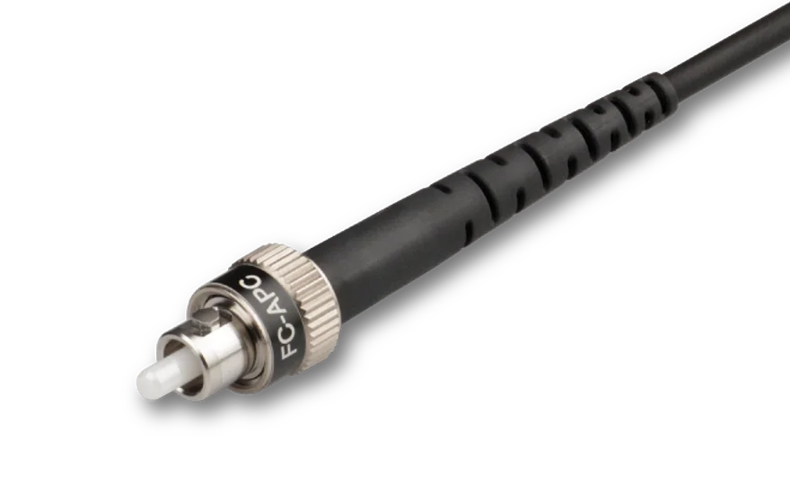
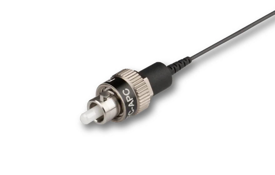
Representative product images. Individual product images are found on the individual product pages.
![]() RGB
RGB
![]() PM
PM
Features
Broadband polarization-maintaining, single-mode fiber cable PMC-RGB with Gaussian intensity distribution and low-stress fiber connectors.
- Special broadband fiber RGB with an operational wavelength range 400-680 nm
- Pure Silica core fibers with low attenuation for wavelengths < 460 nm
- High PER fiber cables
- Measured values for fiber NA: NAe2
- Special fibers with small NA for smaller power density in the fiber core
- Fiber patch cable with Ø 900 µm buffer or as Ø 3 mm Cable with Kevlar strain-relief
- Customer-specified connectors type FC, AVIM (comp. to LSA) or E2000 with 0°-polish or 8°-polish
- Polarization axis is indicated by connector index key (slow axis), only for Type FC connectors
- Amagnetic titanium connectors for connectors of type FC PC or FC APC
- End caps for a smaller power density at the fiber end-faces
Description
Broadband polarization-maintaining, single-mode fiber cables PMC-RGB with Gaussian intensity distribution and low-stress fiber connectors.
RGB Fiber The fiber is a polarization-maintaining, single-mode fiber, defined by its NA and its cut-off wavelength. The nom. NA is specified by the fiber manufacturer. Additionally the effective numerical NAe2 is measured for each fiber batch by Schäfter+Kirchhoff. The fiber has a pure silica core fiber with a cut off below a wavelength of 400 nm. It is suitable for wavelengths up to 680 nm. However, at long wavelength this fiber is quite sensitive to disturbances, such as bending or stress.
During the manufacturing process of fiber cables of type PMC-400RGB additional measures are taken to guarantee a high performance even at high wavelengths. Additional tests are performed to document that the fiber performance is high over the whole wavelength range.
Fiber Cable
The fiber length can be customer-specified (there is a minimum fiber length). The polarization-maintaining fiber cables are offered as Ø 900 µm buffer in black, or a Ø 3 mm cable in black with Kevlar strain-relief.
Fiber Connectors For each fiber end the fiber connectors can be selected from a wide range of connector types (FC, DIN or AVIO) with 0°-polish or 8°-polish. All fiber connectors of type FC assembled by Schäfter+Kirchhoff have an alignment index (key). The wide key (type "N") fiber connector has an alignment index (key) of 2.14 mm width. The narrow key (type "R") fiber connector has an alignment index (key) of 2 mm width. Special fiber connectors are available so that the fiber cable is vaccum compatible down to 10-7 mbar (only Ø 900 µm buffer fiber cables).
High PER fibers During the manufacturing of PM fibers, great care is taken to ensure a high PER. Typical PER values are ≥21 dB to ≥ 26 dB depending on wavelength and connector type.
End Caps The fiber connectors can be equipped with an end cap connector. This means that a short piece of fiber (< 300 µm) without a core is spliced onto the polarization-maintaining fiber. Without a fiber core to confine the beam, the mode field diameter of the beam already starts to diverge within the fiber end cap, significantly reducing the power density at the fiber end-face.
Amagnetic fiber connectors For FC PC or FC APC type connectors amagnetic versions completely made of titanium can be selected. Those connectors have a ceramic ferrule.
Technotes
- Numerical Aperture / Effective Numerical ApertureWhy is it best to define an effective numerical aperture NAe2?
- Typical effective Numerical AperturesTypical values for the effective numerical aperture
- Cut-off wavelengthDefintion of cut-off wavelength and the fiber working range
- Mode field diameterDefinition of mode field diameter MFD
- MFD and NA Wavelength DependencyHow do MFD and NA vary with wavelength?
- Mismatch / NA Mismatch and OverlapOverlap and coupling efficiency when using fibers of different NA, different Mode field or different focal lengths
- Fiber AttenuationAttenuation of single-mode and PM fibers depending on wavelength.
- Pure Silica core fibers (Si)Pure silica core fibers (Si)
- Polarization-maintaining Fibers (PM Fibers)Why are some fibers polarization-maintaining?
- Characterizing Polarization-maintaining Fibers (PM Fibers)How to characterize PM fibers.
- RGB Polarization-maintaining FibersWhat is an RGB PM fiber?
- High Power PhenomenaStimulated Brillouin Scattering and fiber end-face effects
- End cap fibersWhat are end caps and why should I use them?
- Fiber Patch Cable TypesDetails on the structure of 3 mm and 900 µm fiber cables.
- Fiber Connector OptionsFC, AVIM and E2000
- Amagnetic fiber connectorsSpecial features of titanium connectors
- Connecting single-mode and PM fibers to a fiber couplerHow to correctly insert a fiber into the receptacle of a fiber coupler
FAQ
- Connector Type FC PC and FC APC
- How do I attach a fiber cable?
1. To prevent damage to the sensitive fiber end-face, always insert the fiber connector`s ferrule at an angle, with the connector key properly aligned to the receptacle notch.
2. When the ferrule tip is safely located in the inner cylinder of the receptacle, align the connector to the receptacle axis and carefully introduce the connector into the fiber coupler.
3. Then, orient the connector key in a way that it is pressed gently onto the right-hand side of the receptacle notch ("right-hand orientation rule").
4. Gently screw on the connector cap nut onto the receptacle until it is finger-tight.
5. Gently tighten the fiber grub screw to reduce the free play of the ferrule in the receptacle. - What is the "right-hand orientation rule"?
When the ferrule tip is safely located in the inner cylinder of the receptacle, align the connector to the receptacle axis and carefully introduce the connector into the fiber coupler.
Then, orient the connector key in a way that it is pressed gently onto the right-hand side of the receptacle notch.
The tightened grub screw and the "right-hand orientation rule" for the connector, ensure a high reproducibility in mode field position and angle, which is especially important for attaching and reattaching polarization-maintaining fibers reproducibly. - Can I attach a narrow key fiber cable to a fiber coupler with a wide key receptacle?
Yes, you can- without any problem. Simply adhere to the "right-hand orientation rule".
Generally, with any FC PC or FC APC type connector there is a freeplay when inserting the fiber into the fiber coupler. The free play in between the connector ferrule and receptacle is only a few microns, but necessary for inserting the ferrule without force. There is a difference between the receptable and key width for wide key (2.14 mm) and narrow key (2.0 mm) fibers. If you follow the so-called "right-hand orientation rule" you can reproducibly attach and reattach even PM fibers with narrow key receptacle to fiber couplers with wide key receptacle without difficulty.
"Right-hand orientation rule":
When the ferrule tip is safely located in the inner cylinder of the receptacle, align the connector to the receptacle axis and carefully introduce the connector into the fiber coupler. Then, orient the connector key in a way that it is pressed gently onto the right-hand side of the receptacle notch. The tightened grub screw and the "right-hand orientation rule" for the connector, ensure a high reproducibility in mode field position and angle, which is especially important for attaching and reattaching polarization-maintaining fibers reproducibly. - Can I use an end cap fiber with a mating sleeve?
Since the radiation has already started to diverge within the end cap, a simple mating is no longer possible. Please use a fiber-to-fiber coupler in this case.
- How do I attach a fiber cable?
- What is the minimum bend radius for my fiber cable?
- PM fibers
- I look at my fiber end face and do not see a Panda structure? Why is that?
Chances are, that the fiber is equipped with end caps, that do not have a Panda structure themselves. The Panda structure within the actual fiber cable is visble with special microscopes only.
- I look at my fiber end face and do not see a Panda structure? Why is that?
- PM fiber coupling
- Can I also couple into the fast axis of a PM fiber cable?
Conventionally the linearly polarized laser radiation is coupled into the slow axis because of its lower sensitivity to fiber bending.
You can also couple light into the fast axis of a PM fiber cable. However, the bandwidth of the fiber is severly reduced and it is only advisable to couple in a wavelength close to the ccut-off.
Please also keep in mind that Schäfter+Kirchhoff only specifies and tests as well as supplies measurement data for radiation coupled into the slow fiber axis. Measurement and test result will vary for coupling into the fast axis.
- Can I also couple into the fast axis of a PM fiber cable?
Accessories
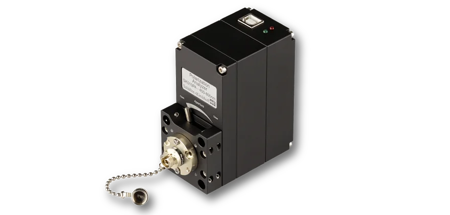
Measurement tool for coupling into polarization-maintaining fiber cables
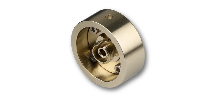
Fiber Adapters without Optics
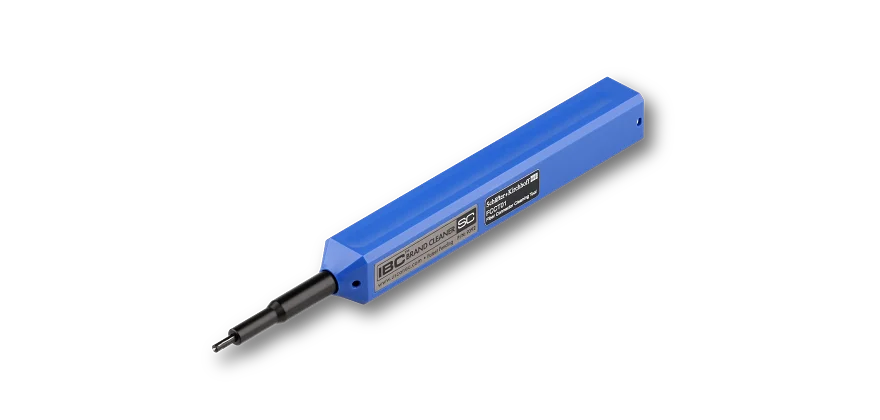
Fiber connector cleaning tool

