Cameras (original) (raw)
Next: Building cameras Up: The Vision Package Previous: The Vision Package Contents The camera modules are separated into single and double precision versions. The double precision camera structure is defined in
#include <gandalf/vision/camera.h>and the single precision version in
#include <gandalf/vision/cameraf.h>The Gandalf camera defines the transformation from camera 3D coordinates into image coordinates and back again. Ten camera models are defined, all using the assumption that the projected position in the image is independent of the depth. The camera structure (double precision floating point version) is as follows:
  /**
    * \brief Structure containing camera parameters.
    */
  typedef struct Gan_Camera
  {
     /// Type of camera
     Gan_CameraType type;

     /// parameters of linear camera

     /// focal distance in x/y pixels
     double fx, fy;

     /// image centre x/y coordinates
     double x0, y0;

     /// third homogeneous image coordinate
     double zh;

     /**
      * \brief Supplementary parameters for non-linear camera models.
      *
      * The thresholds are the square \f$ R^2 \f$ of the undistorted radial
      * camera coordinate \f$ R \f$ where the first reversal of distortion occurs
      * (\a thres_R2), and the similar threshold on the distorted radial
      * distance \f$ d\:R \f$, involving both the distortion coefficient
      * \f$ d \f$  and \f$ F \f$ (thres_dR), at the same reversal point.
      * Both thresholds are set to \c DBL_MAX if there is no reversal.
      */
     union
     {
        struct
        {
           /// Distortion coefficients
           double K1;

           /// Thresholds on \f$ R^2 \f$ and \f$ d\:R \f$
           double thres_R2, thres_dR;

           /// Outer linear model parameters
           double outer_a, outer_b;
        } radial1;

        struct
        {
           /// Distortion coefficients
           double K1, K2;

           /// Thresholds on \f$ R^2 \f$ and \f$ d\:R \f$
           double thres_R2, thres_dR;

           /// Outer linear model parameters
           double outer_a, outer_b;
        } radial2;

        struct
        {
           /// Distortion coefficients
           double K1, K2, K3;

           /// Thresholds on \f$ R^2 \f$ and \f$ d\:R \f$
           double thres_R2, thres_dR;

           /// Outer linear model parameters
           double outer_a, outer_b;
        } radial3;

        struct { double cxx, cxy, cyx, cyy; } xydist4;
     } nonlinear;

     /// gamma value of images taken using this camera
     double gamma;

     /// point functions
     struct
     {
        /// point projection function
        Gan_Bool (*project) ( struct Gan_Camera *camera,
                              Gan_Vector3 *X, Gan_Vector3 *p,
                              Gan_Matrix22 *HX, struct Gan_Camera HC[2],
                              int *error_code );

        /// point back-projection function
        Gan_Bool (*backproject) ( struct Gan_Camera *camera,
                                  Gan_Vector3 *p, Gan_Vector3 *X,
                                  int *error_code );

        /// function to add distortion to a point
        Gan_Bool (*add_distortion) ( struct Gan_Camera *camera,
                                     Gan_Vector3 *pu, Gan_Vector3 *p,
                                     int *error_code );

        /// function to remove distortion from a point
        Gan_Bool (*remove_distortion) ( struct Gan_Camera *camera,
                                        Gan_Vector3 *p, Gan_Vector3 *pu,
                                        int *error_code);
     } point;

     /// line functions
     struct
     {
        /// line projection function
        Gan_Bool (*project) ( struct Gan_Camera *camera,
                              Gan_Vector3 *L, Gan_Vector3 *l );

        /// line back-projection function
        Gan_Bool (*backproject) ( struct Gan_Camera *camera,
                                  Gan_Vector3 *l, Gan_Vector3 *L );
     } line;
  } Gan_Camera;
The single precision version Gan_Camera_f is defined similarly. The camera models are defined in <gandalf/vision/camera_defs.h>, and are
  /**
   * \brief Camera models supported by Gandalf.
   */
  typedef enum
  {
     /// linear camera model
     GAN_LINEAR_CAMERA,

     /// one parameter K1 of radial distortion
     GAN_RADIAL_DISTORTION_1,

     /// two parameters K1,K2 of radial distortion
     GAN_RADIAL_DISTORTION_2,

     /// three parameters K1,K2,K3 of radial distortion */
     GAN_RADIAL_DISTORTION_3,

     /// one parameter K1 of inverse radial distortion
     GAN_RADIAL_DISTORTION_1_INV,

     /// stereographic projection
     GAN_STEREOGRAPHIC_CAMERA,

     /// equidistant projection
     GAN_EQUIDISTANT_CAMERA,

     /// sine-law projection
     GAN_SINE_LAW_CAMERA,

     /// equi-solid angle projection
     GAN_EQUI_SOLID_ANGLE_CAMERA,

     /// distortion model as used by 3D Equalizer V4
     GAN_XY_DISTORTION_4,
  } Gan_CameraType;
The linear and radial distortion models are standard models. The stereographic, equidistant, sine law and equi-solid angle models are wide-angle camera models from [#!Fleck:TR94!#].
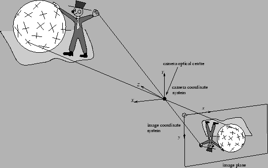
The coordinate frames are illustrated in Figure 5.1.
**Figure 5.1:**Illustration of coordinate frames in projection from camera 3D frame into the image.
 |
|---|
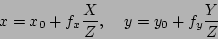
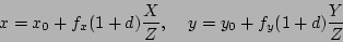
The linear camera model is the simplest standard camera model. It defines the following model relating camera 3D coordinates  to image coordinates
  :
:
 |
(5.1) |
|---|
This equation derives from the similar triangles apparent in the geometrical model illustrated in Figure 5.2. The image centre coordinates  and focal distance parameters
  correspond to the similarly named x0, y0 and fx, fy fields in the Gan_Camera structure. The normal way to write the linear model is in homogeneous coordinates, introducing the third image coordinate
  , which can be identified with the zh field of the Gan_Camerastructure:
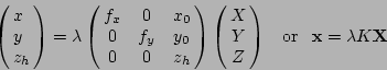
The  parameter can be eliminated, to recover Equation 5.1. can be set to one, but a good rule of thumb is to set it to roughly half the range of image
  coordinates, so that all the image coordinates will be scaled in approximately the same way, which can reduce truncation error in certain situations.
 is known as the camera calibrarion matrix:
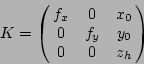
Note the units the elements of .  and
and  both represent the same distance, the perpendicular distance from the image plane to the optical centre, but they are measured in image
  and
and  pixels respectively.
 is the position of the image centre in the image direction and measured in image pixels, and similarly for
  . Note also that and do not measure the focal length of the camera. The focal length is purely a property of the lens system. Under normal circumstances the focal distance will be shorter than the focal length, unless the camera is focussing at infinity when the two distances will be the same.
The linear model is an ``ideal'' model, corresponding to a perfect pinhole camera. It is safe to use this model when the focal length of the lens is large. In practice there will be non-linear distortions, and the simplest model of distortion is that it is purely radial, i.e. directed directly towards or away from the centre of the image5.1A simple model of this distortion is
 |
(5.2) |
|---|
where
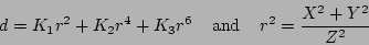
Here  represents the non-linear distortion. The camera modelsGAN_RADIAL_DISTORTION_1, GAN_RADIAL_DISTORTION_2and GAN_RADIAL_DISTORTION_3represent the above distortion model with respectively
  only, both &
  and all of , and
  . Once a camera has been created, it can be used to project from camera to image coordinates, or to back-project from image out into camera coordinates. Note that although the projection is apparently from a 3D space onto a 2D space, you should think instead of a projection between two 2D spaces. All camera 3D points along a straight line through the optical centre project to the same image point, so the projection is between the image plane and the space of rays in camera 3D space through the optical centre, a 2D space of rays.
Subsections
- Building cameras
- Projecting points and lines
- Adding/removing camera distortion
- Building the camera calibration matrix
- Converting cameras between precisions
Next: Building cameras Up: The Vision Package Previous: The Vision Package Contents
2006-03-17