Apply Code and Deployment Configurations to Models - MATLAB & Simulink (original) (raw)
Main Content
In the previous examples, you created configurations that describe the code that you want to generate, including a set of model configuration parameters a code interface configuration. Now configure the models in your system to generate code by connecting them to these configurations.
This example shows how to apply a service interface configuration to code generation models. If you adapt this workflow to your own project and your deployment goals require a different type of code interface configuration, see these links:
- Data interface configuration — C Data Code Interface Configuration for Model Interface Elements and Choose Data Configuration Approach.
- AUTOSAR component configuration — AUTOSAR Component Configuration (AUTOSAR Blockset).
Share Code Configurations with Code Generation Models
Each model in the hierarchy references the freestanding configuration in the data dictionary, which you set up in Share Code Generation Settings Among the Model Hierarchy. Confirm that the shared configuration uses the Embedded Coder Dictionary that you defined in Create an Embedded Coder Dictionary to Contain Interface Definitions.
- If you have not already done so, follow the steps in the previous part of the workflow, Define the Interfaces Between the Generated Code and Your Deployment Platform, or run the script.
openExample("EvPowertrainController")
CoderDictForEvPowertrainModel - Open the model
EvPowertrainControllerand the Embedded Coder® app. - From the
EvPowertrainControllermodel, on the C Code tab, clickSettings. - In the dialog box for the configuration reference, on the Code Generation pane, check that the**Shared coder dictionary** parameter is set to
CoderDict.sldd. ClickOK.
The models that use the shared configuration set also use the configuration interface that you defined in the Embedded Coder Dictionary in CoderDict.sldd. Because the dictionary uses a service interface configuration, models that use the configuration set generate code that uses service interfaces.
Select Deployment Types in the Model Hierarchy
Models at different levels in the model hierarchy can have different requirements for the resulting code to run on the target platform. A_deployment type_ indicates how the generated code for a model interacts with the target platform and the code generated from other models. The deployment type also determines which types of code interfaces are available for the model. The deployment types are:
- Component — The top model from which the code generator produces code. The code generator produces a standalone algorithm that runs on the target platform. The component code exposes its interface to other components in the system and to platform services.
- Subcomponent — A model reference that a component model uses. The generated code entry points are symbolically scoped to the parent component and are not exposed to the platform.
- Automatic — Embedded Coder determines the deployment type based on the model hierarchy context.
To configure the deployment types for the model hierarchy:
- From the
EvPowertrainControllermodel, on the C Code tab, in thePrepare section, click theComponent button. This button shows the deployment type for the model that is in the canvas. - From the Deployment Type menu, select Set Up Deployment Type for Model Hierarchy.
- In the Set up deployment type for model hierarchy dialog box, expand the
EvPowertrainControllermodel to see the model hierarchy.
For this example, both models are configured as deployable, which means that both are intended for code generation. If your hierarchy includes models that are not intended for code generation, such as a plant model, you can clear the deployable options for those models.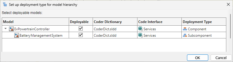
The top modelEvPowertrainControlleruses the deployment type Component and the referenced modelBatteryManagementSystemuses the deployment typeSubcomponent. The deployment settings were set up when you created the service interface dictionary for the component model.
For this example, do not change the deployment types. - Click OK.
Apply Code Interface Definitions to Models
To specify the interface of the generated code for elements of your model, map the model elements to the code interface definitions that you defined in the Embedded Coder Dictionary.
- From the
EvPowertrainControllermodel, on the C Code tab, click > . The Code Mappings - Component Interface table shows the elements of the model and their associated code interface definitions. You can see different types of model elements by clicking the tabs above the table.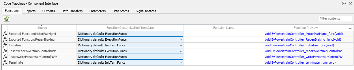
- On the Function tab, examine the function templates listed in the Function Customization Template column. By default, the model functions use the templates that you created and selected as dictionary default definitions in Define Function Interfaces.
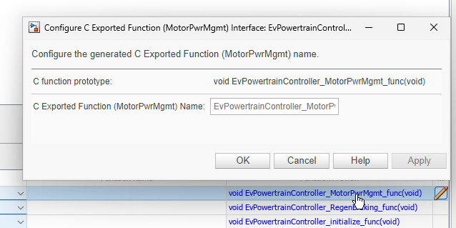
- Click the function name link in the Function Preview column. You can further configure the prototypes for the generated function names and, for certain types of code interfaces, the function arguments.
- On the Inports andOutports tabs, confirm that the mapping uses the sender and receiver services that you specified as dictionary default definitions.
- To override the default mapping for a model element, select a different code interface definition from the table. For example, click the Data Transfers tab. In the Data Transfer Service column, click the row for
DataTransferAtRegenBrakingOutport1. From the drop-down list, selectDataTransferExample2. For that data transfer interface, the generated code communicates data immediately during execution.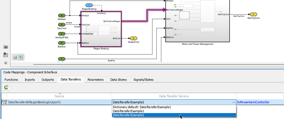
The code mapping enables you to easily configure your models to use the code interface definitions that you created for your target platform services. You can configure many models at once by specifying default definitions in the shared Embedded Coder Dictionary, while maintaining the flexibility to override the default settings in the mappings for individual model elements.