Board-Specific Setup Information - MATLAB & Simulink (original) (raw)
Main Content
To start a AMD® FPGA from an SD card, you must configure the jumpers or switches. The jumper settings are different for each board.
Prepare Hardware Board
Before you configure the FPGA board, make sure to:
- Plug in the power cord.
- If you are using a JTAG connection, connect the FPGA board to the host computer using a JTAG cable.
- If you are using an Ethernet connection, connect the FPGA board to the host computer using an Ethernet cable.
- Insert SD card in the SD card slot.
- Connect the USB cable to the USB-UART port.
Hardware Configuration
When you make the jumper or switch settings for the board, make sure that the board is turned off. To boot the board the from SD card, make the switch or jumper setting for the respective board as given below.
![]() Xilinx Zynq ZC702 Evaluation Kit
Xilinx Zynq ZC702 Evaluation Kit
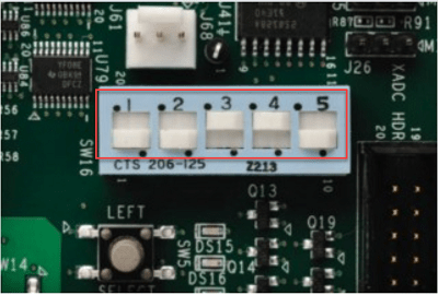
To set up the Xilinx® Zynq® ZC702 evaluation kit to boot from an SD card, configure the SW16 switches according to the ZC702 Evaluation Board User Guide. Set the switch positions as shown in the table.
| Boot Mode | SW16 Switch Position [1:5] |
|---|---|
| SD | 0, 0, 1, 1, 0 |
![]() Xilinx Zynq ZC706 Evaluation Kit
Xilinx Zynq ZC706 Evaluation Kit
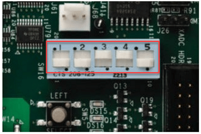
To set up the Xilinx Zynq ZC706 evaluation kit to boot from an SD card, configure the SW16 switches according to ZC706 Evaluation Board User Guide. Set the switch positions as shown in the table.
| Boot Mode | SW16 Switch Position [1:5] |
|---|---|
| SD | 0, 0, 1, 1, 0 |
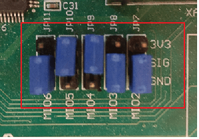
To set up ZedBoard™ to boot from SD card, configure JP[7:11] jumpers position as shown in the table, where 1 represents 3V3 and0 represents GND.
| Boot Mode | Jumper Position JP[11:7] |
|---|---|
| SD | 0, 1, 1, 0, 0 |
![]() Xilinx Versal AI Core Series VCK190 Evaluation Kit
Xilinx Versal AI Core Series VCK190 Evaluation Kit
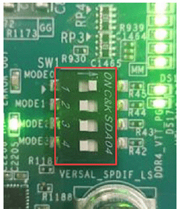
To set up the Xilinx Versal® AI Core Series VCK190 evaluation kit to boot from SD card, configure the SW1 switches according to VCK190 Evaluation Board User Guide. Set the switch positions as shown in the table, where 1 represents Low and0 represents High.
| Boot Mode | Mode Pins [3:0] | SW1 Switch Position [4:1] |
|---|---|---|
| SD | 1, 1, 1, 0 | off, off, off, on |
![]() Xilinx Zynq UltraScale+ MPSoC ZCU102 Evaluation Kit
Xilinx Zynq UltraScale+ MPSoC ZCU102 Evaluation Kit
To set up the Xilinx Zynq UltraScale+™ MPSoC ZCU102 evaluation kit to boot from an SD card, configure the SW6 switches according to ZCU102 Evaluation Board User Guide. Set the switch positions as shown in the table, where 1 represents Low and0 represents High.
| Boot Mode | Mode Pins [3:0] | SW6 Switch Position [4:1] |
|---|---|---|
| SD | 1, 1, 1, 0 | off, off, off, on |
![]() Xilinx Zynq UltraScale+ RFSoC ZCU111 Evaluation Kit
Xilinx Zynq UltraScale+ RFSoC ZCU111 Evaluation Kit
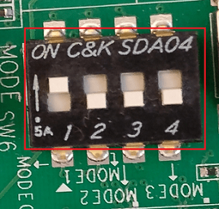
To set up the Xilinx Zynq UltraScale+ RFSoC ZCU111 evaluation kit to boot from an SD card, configure the SW6 switches according to ZCU111 Evaluation Board User Guide. Set the switch positions as shown in the table, where 1 represents Low and 0 represents High.
| Boot Mode | Mode Pins [3:0] | SW6 Switch Position [4:1] |
|---|---|---|
| SD | 1, 1, 1, 0 | off, off, off, on |
To set up the cable connections for the digital-to-analog converter (DAC) and analog-to-digital converter (ADC) loopback data capture, configure the XM500 Balun card as shown in these figures.
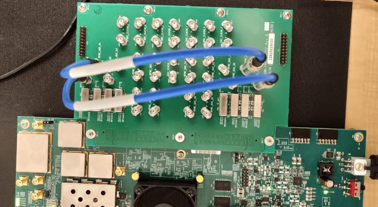
The ZCU111 evaluation kit includes a Balun board (HW-FMC-XM500) that has differential and single-ended SMA connections. Because the differential connection does not have AC coupling capacitors, the connections require a DC blocker. Some of the single-ended SMA connections have RF filters that can attenuate frequencies and alter phase. For more information, see Appendix D inZCU111 Evaluation Board User Guide.
![]() Xilinx Zynq UltraScale+ RFSoC ZCU216 Evaluation Kit
Xilinx Zynq UltraScale+ RFSoC ZCU216 Evaluation Kit
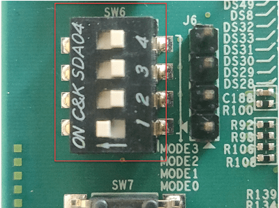
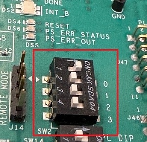
To set up the Xilinx Zynq UltraScale+ RFSoC ZCU216 evaluation kit to boot from an SD card, configure the SW2 switches according to ZCU216 Evaluation Board User Guide. Set the switch positions as shown in the table, where 1 represents Low and 0 represents High.
| Boot Mode | Mode Pins [3:0] | SW2 Switch Position [4:1] |
|---|---|---|
| SD | 1, 1, 1, 0 | off, off, off, on |
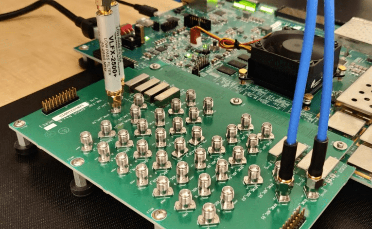
To set up the cable connections for the digital-to-analog converter (DAC) and analog-to-digital converter (ADC) loopback data capture:
- Configure the XM655 Balun card as shown in this figure.
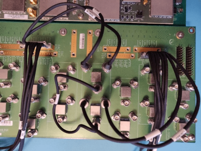
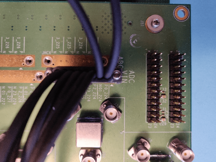
- Configure the DAC and ADC connections as shown in the figure. In this cable setup, the HDL design transmits out of DAC Tile-1 Channel-3 and receives from ADC Tile-0 Channel-0. The DAC Tile-1 Channel-3 uses the 3_229 P/N differential signals on the JHC2 connector of the XM655 card. The ADC Tile-0 Channel-0 uses the 0_224 P/N differential signals on the JHC5 connector. Connect both DAC and ADC signals to one of the 10MHz-1GHz connectors, and connect the cable to these two connectors.
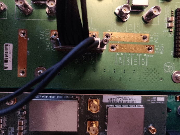
- This figure shows the loopback example in more detail.
The ZCU216 evaluation kit includes several attachment cards that you must install. These attachments include the Clock104 board, XM650 N79 loopback board, and the XM655 breakout add-on card. If you do not install the Clock104 board, the RFSoC board does not function. You can use either an XM650 or an XM655 Balun card. You must decide which Balun card to use for your test setup. The XM655 card has the option of using differential connections, which requires DC blockers or single-ended SMA by using the provided Balun filters. For more information, see the Xilinx documentation. To see the installation procedures of these attachment cards, see RF DC Evaluation Tool for ZCU216 board - Quick start on the AMD website. For part identification, see ZCU216 Evaluation Kit - What's Inside on the Xilinx website.