Merge - Combine multiple signals into single signal - Simulink (original) (raw)
Combine multiple signals into single signal
Libraries:
Simulink / Signal Routing
HDL Coder / Ports & Subsystems
Description
The Merge block combines inputs into a single output. The output value at any time is equal to the most recently computed output of its driving blocks. Specify the number of inputs by setting the Number of inputs parameter.
Use a Merge block to interleave input signals that update at different times into a combined signal in which the interleaved values retain their separate identities and times. To combine signals that update at the same time into an array or matrix signal, use a Concatenate block.
Guidelines for Using the Merge Block
When you use the Merge block, follow these guidelines:
- Always use conditionally executed subsystems to drive Merge blocks, without any intervening blocks.
- Ensure that at most one of the driving conditionally executed subsystems executes at any time step.
- Ensure that all input signals have the same sample time.
- Do not branch a signal that is input to a Merge block.
- Do not log a signal that is input to a Merge block.
- Do not specify the block execution priority of a Merge block. For more information, see Specify Block Execution Order, Execution Priority, and Tag.
- For all conditionally executed subsystem Outport blocks that driveMerge blocks, set Output when disabled to
held. - If the output of a Model block is coming from aMATLAB Function block or a Stateflow® chart, do not connect that output port to the input port of the Merge block.
- The Merge block supports merging signals in different tasks to a root Outport block.
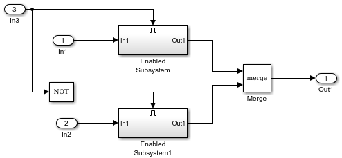
For each input of a Merge block, the topmost nonvirtual source must be a conditionally executed subsystem (not including a For Iterator or While Iterator subsystem).
The next diagram shows valid Merge block usage, merging signals from two conditionally executed subsystems.
Bus Support
The Merge block is a bus-capable block. The inputs can be virtual or nonvirtual bus signals subject to these restrictions:
- The number of inputs must be greater than one.
- Initial output must be zero, a nonzero scalar, or a finite numeric structure.
- The Allow unequal port widths check box must be cleared.
- All inputs must be buses and must be equivalent (same hierarchy with identical names and attributes for all elements).
All signals in a nonvirtual bus input to a Merge block must have the same sample time. You can use a Rate Transition block to change the sample time of an individual signal, or of all signals in a bus.
Merging S-Function Outputs
The Merge block can merge a signal from an S-Function block only if the memory used to store the output from the S-Function block is reusable. Simulink® displays an error message if you attempt to update or simulate a model that connects a nonreusable port of an S-Function block to aMerge block. See ssSetOutputPortOptimOpts.
Multi-tasked Root Outputs
A Merge block connected to a root Outport block allows merging signals in different tasks by allowing those signals to write to the rootOutport block simultaneously. A Union sample time of the sources is assigned to the Merge block.
All the sources of the Merge block that are in the same task should be inside conditionally executed subsystems that should not output simultaneously in the same time step.
Examples
This example shows a Merge block with inputs from two atomic subsystems.
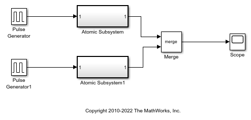
Each Atomic Subsystem block contains an enabled subsystem. This satisfies the requirement that inputs to a Merge block are from a conditionally executed subsystem.
This example shows how to use the Merge block with inputs ports that have different widths. If you select Allow unequal port widths, the block accepts scalar and vector inputs having differing numbers of elements. You can specify an offset for each input signal relative to the beginning of the output signal. The width of the output signal is:

where  are the widths of the input signals, and
  are the offsets.
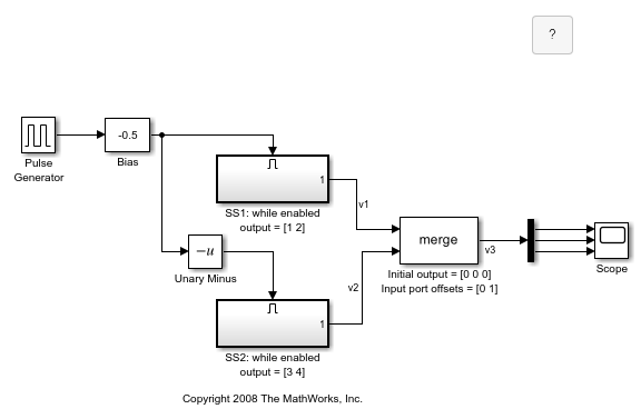
The Merge block has the following output width.

In this example, the offset of  is
is 0 and the offset of  is
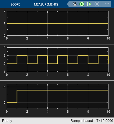
is 1. The Merge block maps the elements of to the first two elements of  and the elements of to the last two elements of . Only the second element of is effectively merged, as show in the scope output.
If you use Simplified Initialization Mode, you must clear the Allow unequal port widths check box. The input port offsets for all signals must be zero.
Extended Examples
Limitations
- All signals that connect to a Merge block are functionally the same signal. Therefore, they are subject to the restriction that a given signal can have at most one associated signal object. See Simulink.Signal for more information.
- Run-time diagnostics do not run if the inputs to a Merge block are from a single initiator. For example, a single initiator could be a Stateflow chart executing function-call subsystems that are connected to aMerge block.
- Do not set the outports of conditionally executed subsystems being merged to reset when disabled. This action can cause multiple subsystems to update the block at the same time. Specifically, the disabled subsystem updates theMerge block by resetting its output, while the enabled subsystem updates the block by computing its output.
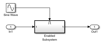
To prevent this behavior, set the Outport block parameter Output when disabled toheldfor each conditionally executed subsystem being merged. - A Merge block does not accept input signals whose elements have been reordered or partially selected, as shown in the next diagram.

- Do not connect input signals to the block that have been combined outside of a conditionally executed subsystem.
You can use an array of buses as an input signal to a Merge block with these limitations:
- Allow unequal port widths — Clear this parameter.
- Initial condition — You can specify this parameter using:
- The value
0. In this case, each of the individual signals in the array of buses use the initial value0. - An array of structures that specifies an initial condition for each of the individual signals in the array of buses.
- A scalar structure that specifies an initial condition for each of the elements that the bus type defines. Use this technique to specify the same initial conditions for each of the buses in the array.
- The value
Ports
Input
First input signal merged with the other input signals.
Data Types: single | double | half | int8 | int16 | int32 | int64 | uint8 | uint16 | uint32 | uint64 | Boolean | fixed point | enumerated | bus | image
_n_th input signal merged with the other input signals.
Data Types: single | double | half | int8 | int16 | int32 | int64 | uint8 | uint16 | uint32 | uint64 | Boolean | fixed point | enumerated | bus | image
Output
Output signal merged from the input signals.
Data Types: single | double | half | int8 | int16 | int32 | int64 | uint8 | uint16 | uint32 | uint64 | Boolean | fixed point | enumerated | bus | image
Parameters
Specify the number of input signals to merge. The block creates a port for each input signal.
Programmatic Use
| Block Parameter: Inputs |
|---|
| Type: character vector |
| Values: integer |
| Default: '2' |
Specify the initial value of the output signal. If you do not specify an initial output value, then initial output depends on the initialization mode and the driving blocks.
In Simplified Initialization Mode, for an unspecified (empty matrix[]) value of Initial output, the block uses the default initial value of the output data type. For information on the default initial value, see Initialize Signal Values. InClassic Initialization Mode, for an unspecified (empty matrix[]) value of Initial output, the initial output of the block equals the most recently evaluated initial output of the driving blocks. Since the initialization ordering for these sources can vary, initialization can be inconsistent for the simulation and the code generation of a model.
Programmatic Use
| Block Parameter: InitialOutput |
|---|
| Type: character vector |
| Values: scalar | vector |
| Default: '[ ]' |
Select this parameter to allow the block to accept inputs having different numbers of elements from each other or from the output. The block allows you to specify an offset for each input signal relative to the beginning of the output signal. The width of the output signal is
max(w1+o1, w2+o2, ... wn+on)
where w1, ...wn are the widths of the input signals and o1, ...on are the offsets for the input signals.
If you clear this parameter, the Merge block accepts only inputs of equal dimensions and outputs a signal of the same dimensions as the inputs.
Note
Do not select this parameter unless your model is using Classic Initialization Mode.
Programmatic Use
| Block Parameter: AllowUnequalInputPortWidths |
|---|
| Type: character vector |
| Values: 'off' | 'on' |
| Default: 'off' |
Enter a vector to specify the offset of each input signal relative to the beginning of the output signal.
Dependencies
To enable this parameter, select Allow unequal port widths.
Programmatic Use
| Block Parameter: InputPortOffsets |
|---|
| Type: character vector |
| Values: scalar | vector |
| Default: '[ ]' |
Block Characteristics
| Data Types | Boolean | bus | double | enumerated | fixed point | half | image | integer | single | string |
|---|---|---|---|---|---|---|---|---|---|
| Direct Feedthrough | yes | ||||||||
| Multidimensional Signals | yes | ||||||||
| Variable-Size Signals | no | ||||||||
| Zero-Crossing Detection | no |
Extended Capabilities
In the code generation workflow, when the Merge block receives a constant value and non-constant sample times, one of these conditions must hold. Otherwise Simulink displays an error.
- The source of the constant value is a grounded signal.
- The source of the constant value is a constant block with a non-tunable parameter.
- There is only one constant block that feeds theMerge block.
- All other input signals to the Merge block are from conditionally executed subsystems.
- The Merge block and outport blocks of all conditionally executed subsystems does not specify any initial outputs.
HDL Coder™ provides additional configuration options that affect HDL implementation and synthesized logic.
HDL Architecture
This block has one default HDL architecture.
HDL Block Properties
| ConstrainedOutputPipeline | Number of registers to place at the outputs by moving existing delays within your design. Distributed pipelining does not redistribute these registers. The default is0. For more details, see ConstrainedOutputPipeline (HDL Coder). |
|---|---|
| InputPipeline | Number of input pipeline stages to insert in the generated code. Distributed pipelining and constrained output pipelining can move these registers. The default is0. For more details, see InputPipeline (HDL Coder). |
| OutputPipeline | Number of output pipeline stages to insert in the generated code. Distributed pipelining and constrained output pipelining can move these registers. The default is0. For more details, see OutputPipeline (HDL Coder). |
Code generation not supported when this block is used inside a For Each Subsystem block.
Version History
Introduced before R2006a