Map Variables for Atomic Subcharts and Boxes - MATLAB & Simulink (original) (raw)
An atomic subchart is a graphical object that helps you create reusable subcomponents in a Stateflow® chart. An atomic box is a graphical object that helps you share graphical, truth table, MATLAB®, and Simulink® functions across several charts. Atomic subcharts and boxes are not supported in standalone Stateflow charts in MATLAB. For more information, see Create Reusable Subcomponents by Using Atomic Subcharts and Reuse Functions by Using Atomic Boxes.
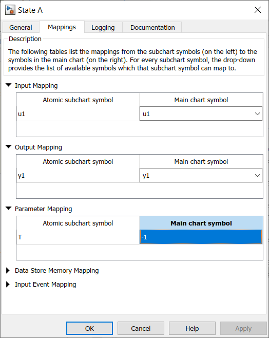
To ensure that each symbol in your atomic subchart or box accesses the correct symbol in the main chart, edit the mapping of subchart symbols. Right-click the subchart or box and select Subchart Mappings. In theMappings tab of the properties dialog box, use theMain chart symbol drop-down list to specify which symbol in the main chart corresponds to each symbol in the subchart. Alternatively, you can type an expression specifying:
- A field of a Stateflow structure. See Index and Assign Values to Stateflow Structures.
- An element of a vector or matrix. See Operations for Vectors and Matrices in Stateflow.
- Any valid combination of structure fields or matrix indices, such as
struct.field(1,2)orstruct.field[0][1].
If you leave the Main chart symbol field empty, then Stateflow attempts to map the atomic subchart symbol to a main chart symbol with the same name.
You can map a symbol in the atomic subchart to a symbol in the main chart that has a different scope. This table lists the possible mappings.
| Atomic Subchart Symbol Scope | Main Chart Symbol Scope |
|---|---|
| Input | Input, Output, Local, Parameter |
| Output | Output, Local |
| Parameter | Parameter |
| Data Store Memory | Data Store Memory, Local |
| Input Event | Input Event |
When you map data store memory in an atomic subchart to local data of enumerated type, you have two options for specifying the initial value of the data store memory:
- In the Data properties dialog box, set the Initial value field for the chart-level local data.
- To apply the default value of the enumerated type, leave theInitial value field empty.
Map Input and Output Data for an Atomic Subchart
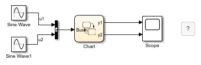
This model contains two Sine Wave blocks that supply input signals to a chart.
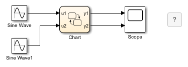
The chart consists of two linked atomic subcharts from the same library.

Both atomic subcharts contain saturator logic to convert an input sine wave to an output square wave of the same frequency.

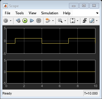
If you simulate the model, the output for y2 is zero.
Because the symbols in atomic subchart A have the same name as the symbols u1 and y1 in the main chart, they map to the correct variables. The symbols in atomic subchart B do not map to u2 and y2 in the main chart, so you must edit the mapping.
- Right-click subchart B and select Subchart Mappings.
- Under Input Mapping, specify the main chart symbol for
u1to beu2. - Under Output Mapping, specify the main chart symbol for
y1to bey2. - Click OK.

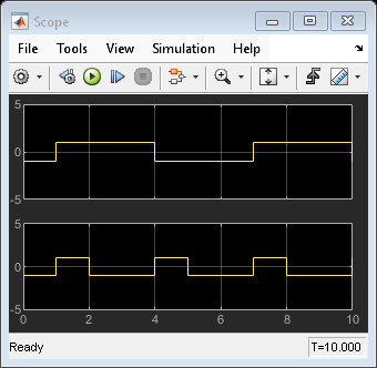
When you run the model again, you get these results.
Map Atomic Subchart Variables to Bus Elements
This model contains two Sine Wave blocks that supply signals through a bus to a chart.
The chart consists of two linked atomic subcharts from the same library. Both atomic subcharts contain saturator logic to convert an input sine wave to an output square wave of the same frequency.

If you simulate the model, you get an error because the u1 inputs in each subchart do not map to any variables in the main chart. To edit the mapping for u1 in each subchart:
- Right-click subchart A and select Subchart Mappings.
- Under Input Mapping, specify the main chart symbol for
u1to be the first element in the bus:BusIn.u1. - Click OK.
- Repeat for subchart B, specifying the main chart symbol for
u1to be the second element in the bus:BusIn.u2.
When you run the model again, you get these results.

Map Atomic Subchart Variables to the Elements of a Matrix
When referring to elements of a vector or matrix, regardless of the action language of the chart, use:
- One-based indexing delimited by parentheses and commas. For example,
A(4,5). - Zero-based indexing delimited by brackets. For example,
A[3][4].
Indices can be numbers or parameters in the chart. The use of other expressions as indices is not supported.
For example, this model contains two Sine Wave blocks that supply signals through a diagonal matrix to a chart.
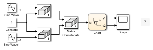
The chart consists of two linked atomic subcharts from the same library. Both atomic subcharts contain saturator logic to convert an input sine wave to an output square wave of the same frequency.
If you simulate the model, you get an error because the u1 inputs in each subchart do not map to any variables in the main chart. To edit the mapping for u1 in each subchart:
- Right-click subchart A and select Subchart Mappings.
- Under Input Mapping, specify the main chart symbol for
u1to be the top-left element in the matrix. The zero-based indexing format for this element isM[0][0]. - Click OK.
- Repeat for subchart B, specifying the main chart symbol for
u1to be the bottom-right element in the matrix. The one-based indexing format for this element isM(2,2).
When you run the model again, you get these results.

Map Atomic Subchart Parameters to Expressions
For parameters in an atomic subchart, you can specify an expression that combines constants, variables in the base workspace, and parameters in the main chart.
For example, this model contains two Sine Wave blocks that supply input signals to a chart.

The chart consists of two linked atomic subchart from the same library. Both atomic subcharts contain saturator logic to convert an input sine wave to an output square wave of the same frequency.

If you simulate the model, you get an error because the parameter T is undefined. To fix this error, specify an expression for T to evaluate in the main chart:
- Right-click subchart A and select Subchart Mappings.
- Under Parameter Mapping, as the value for
T, enter-1. - Click OK.
- Repeat for subchart B, specifying the value of
Tas2.
When you run the model again, you get these results.

Map Atomic Subchart Variables to Data Stores
You can map atomic subchart symbols to top-level elements of Data Store Memory blocks. For example, if a Data Store Memory block contains an array, you can map an atomic subchart symbol to the array, but not to a subarray or individual array elements. For more information about using data stores, see Access Data Store Memory from a Chart.
In this model, a Sine Wave block and a Data Store Memory block supply data to a chart.
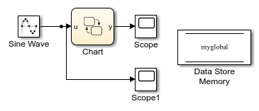
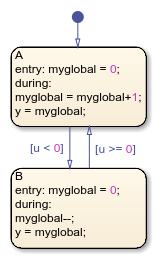
The chart contains two states that read from and write to the Data Store Memory block.
To convert the A state to an atomic subchart, right-click the A state and select Group & Subchart > Atomic Subchart. The chart automatically maps the subchart data store to the main chart data store.
To confirm or change the object that the atomic subchart maps to, right-click the atomic subchart and select Subchart Mappings.

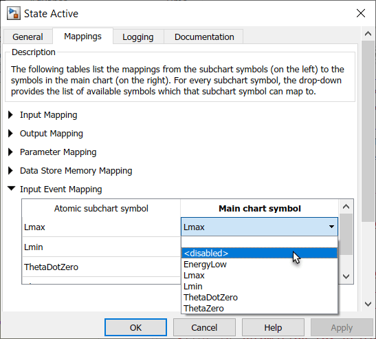
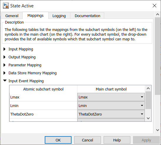
Map Input Events for an Atomic Subchart
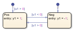
This model contains a Mux block that supplies input events to a chart.
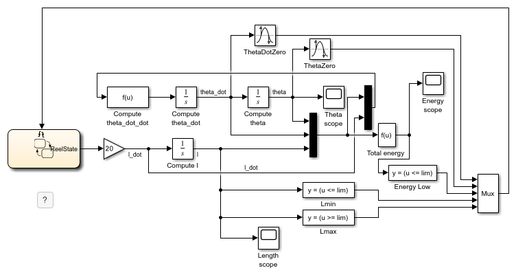
The chart contains two superstates: Active and Inactive. The Active state uses input events to guard transitions between different substates.
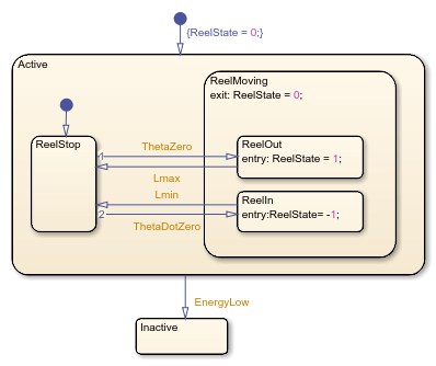
To convert the Active state to an atomic subchart:
- Right-click the
Activestate and select Group & Subchart > Atomic Subchart. - Right-click the atomic subchart and select Subchart Mappings.
- Under Input Event Mapping, map each atomic subchart symbol to the corresponding input event in the main chart.
- Click OK.
Disable Input Events for Atomic Subcharts
Not every input event in an atomic subchart has to correspond to an event in the main chart. For example, you can create a linked atomic subchart that does not use the entire set of events that are defined in the library chart. To disable an input event in an atomic subchart:
- Right-click the atomic subchart and select Subchart Mappings.
- Under Input Event Mapping, in the Main chart symbol drop-down list, select
<disabled>. - Click OK.