Second-Order Section Filter - Implement cascade of second-order section filters - Simulink (original) (raw)
Implement cascade of second-order section filters
Since R2023b
Libraries:
DSP System Toolbox / Filtering / Filter Implementations
Description
The Second-Order Section Filter block implements a cascade of second-order section (SOS) filters in Simulink®. You can specify the numerator and denominator coefficients of the filter in the block parameters dialog box or through input ports.
Examples
Filter a noisy sinusoidal signal using the Second-Order Section Filter block. Obtain the numerator and denominator coefficients of the SOS filter using the Bandpass IIR Filter Design block.
Tune the frequency specifications of the SOS filter during simulation.
Open and Run Model
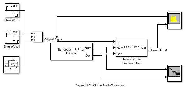
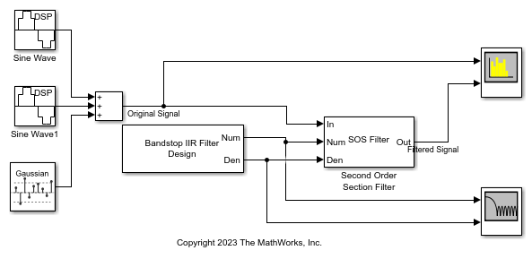
Open the secondordersectionfilter model.
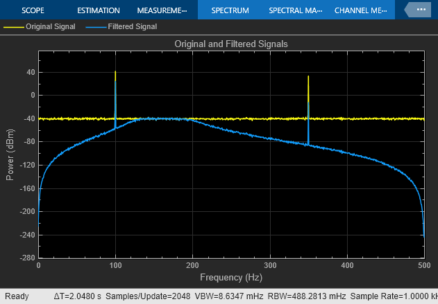
The input signal in the model is a sum of two sine waves with the frequencies of 100 Hz and 350 Hz. The sample rate is 1000 Hz and the number of samples in each frame is 1024. The Random Source block adds zero-mean white Gaussian noise with a variance of 1e-4 to the sum of the sine waves.
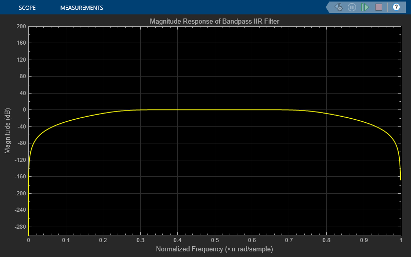
The Bandpass IIR Filter Design block designs a sixth-order bandpass IIR filter with the first and second 3-dB cutoff frequencies of 0.25  rad/sample and 0.75 rad/sample, respectively. The block generates coefficients as a cascade of second-order sections. Visualize the frequency response of the filter using the Filter Visualizer.
Run the model.
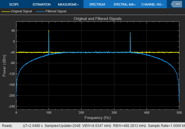
The Second-Order Section Filter block filters the noisy sinusoidal signal. Visualize the original sinusoidal signal and the filtered signal using the Spectrum Analyzer.
Tune Frequency Specifications of SOS Filter
During simulation, you can tune the frequency specifications of the SOS filter by tuning the frequency parameters in the Bandpass IIR Filter Design block. The frequency response of the SOS filter updates accordingly.
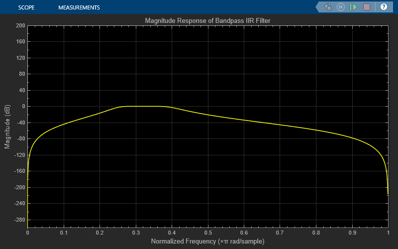
Change the second 3-dB cutoff frequency to 0.4 rad/sample in the Bandpass IIR Filter Design block. To change the parameter values more gradually during simulation, select the Smooth tuned filter parameters check box and specify a smoothing factor in the Bandpass IIR Filter Design block dialog box. The smoothing factor determines the speed at which the parameter values change until they match the desired new value. If you specify a smoothing factor of 0, the block does not smooth the parameter and immediately sets the parameter to the new value. As the smoothing factor approaches 1, the number of smoothing operations, and consequently, the number of filter redesigns increase. This example uses a smoothing factor is of 0.6.
When you change the second 3-dB cutoff frequency to 0.4 rad/sample, the second tone of the sinusoidal signal gets attenuated as it no longer falls in the passband region of the filter.
Filter a noisy sinusoidal signal using the Second-Order Section Filter block. Obtain the numerator and denominator coefficients of the SOS filter using the Bandstop IIR Filter Design block.
Tune the frequency specifications of the SOS filter during simulation.
Open and Run Model
Open the secondordersection_bandstopfilter model.
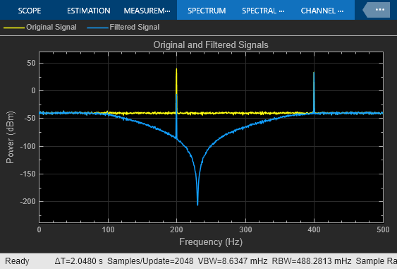
The input signal in the model is a sum of two sine waves with the frequencies of 200 Hz and 400 Hz. The sample rate is 1000 Hz and the number of samples in each frame is 1024. The Random Source block adds zero-mean white Gaussian noise with a variance of 1e-4 to the sum of the sine waves.
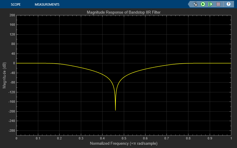
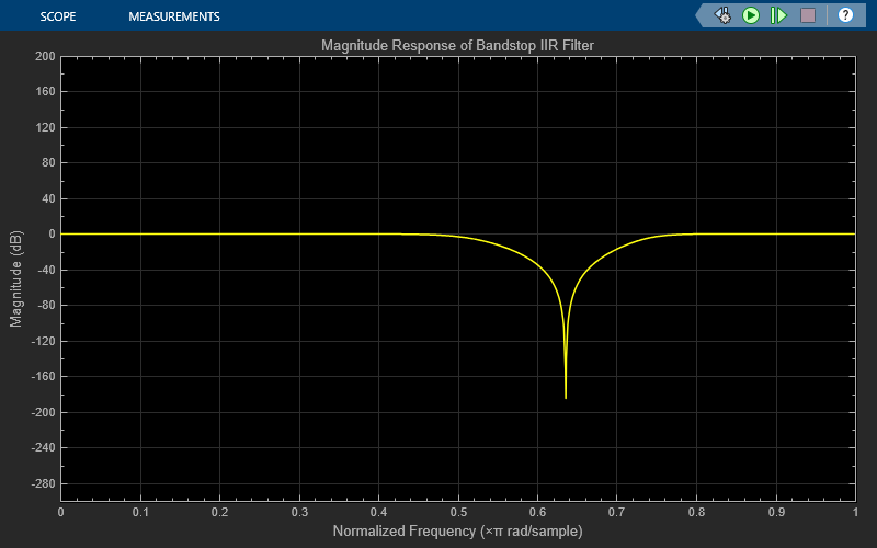
The Bandstop IIR Filter Design block designs a sixth-order bandstop IIR filter with the first and second 3-dB cutoff frequencies of 0.2  rad/sample and 0.75 rad/sample, respectively. The block generates coefficients as a cascade of second-order sections. Visualize the frequency response of the filter using Filter Visualizer.
Run the model.
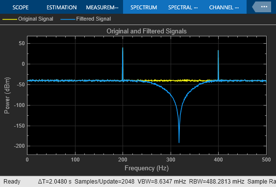
The Second-Order Section Filter block filters the noisy sinusoidal signal. Visualize the original sinusoidal signal and the filtered signal using the Spectrum Analyzer. The first tone is attenuated as it falls in the stopband region of the filter while the second tone remains unaffected as it falls in the passband region of the filter.
Tune Frequency Specification of SOS Filter
During simulation, you can tune the frequency specifications of the SOS filter by tuning the frequency parameters in the Bandstop IIR Filter Design block. The frequency response of the SOS filter updates accordingly.
Change the first 3-dB cutoff frequency to 0.5 rad/sample in the Bandstop IIR Filter Design block. The first tone of the sinusoidal signal now falls in the passband region and is therefore unattenuated.
Ports
Input
Specify the input signal as a vector or a matrix. The input can be a variable-size signal, that is, the frame size of the signal can change during simulation but the number of channels cannot.
This port is unnamed until you set the Coefficient source parameter to Input ports.
Data Types: single | double
Complex Number Support: Yes
Specify the numerator coefficients of the SOS filter as a_P_-by-3 matrix, where P is the number of filter sections. For more details on this input port, seeNumerator.
During simulation, you cannot change the size of the coefficients matrix but you can change the coefficient values.
The size and complexity of the Num andDen inputs must be the same.
Dependencies
To enable this port, set the Coefficient source parameter to Input ports.
Data Types: single | double
Complex Number Support: Yes
Specify the denominator coefficients of the SOS filter as a_P_-by-3 matrix or a P_-by-2 matrix, where_P is the number of filter sections. For more details on this input port, see Denominator.
When you specify a _P_-by-3 matrix, the block always assumes the leading denominator coefficient to be 1. If you specify any other value in the first column, the block ignores this value and treats it as 1. If you specify a_P_-by-2 matrix, the block prepends each row of the matrix with a value of 1.
During simulation, you cannot change the size of the coefficients matrix but you can change the coefficient values.
The size and complexity of the Num andDen inputs must be the same.
Dependencies
To enable this port, set the Coefficient source parameter to Input ports.
Data Types: single | double
Complex Number Support: Yes
Specify the scale values that the block applies before and after each section of the SOS filter as a scalar or a vector with P + 1 elements, where_P_ is the number of filter sections.
If you input a scalar, the block applies this gain value before the first filter section and sets the gain values before all the other sections to1. If you specify a vector of P + 1 values, the block applies each value to a separate section of the filter.
Tunable: Yes
Dependencies
To enable this port, set Coefficient source toInput ports and select the Specify scale values parameter.
Data Types: single | double
Output
Filtered output, returned as a vector or a matrix. The output has the same size and data type as the input. The output signal is complex if the input signal, numerator coefficients, or the denominator coefficients is complex.
This port is unnamed until you set the Coefficient source parameter to Input ports.
Data Types: single | double
Complex Number Support: Yes
Parameters
To edit block parameters interactively, use theProperty Inspector. From the Simulink Toolstrip, on the Simulation tab, in thePrepare gallery, select Property Inspector.
Specify the filter structure as one of these:
Direct form IDirect form I transposedDirect form IIDirect form II transposed
Specify the filter coefficient source as one of these:
Dialog parameters–– Set the filter coefficients and scale values through the Numerator,Denominator, and Scale Values parameters in the block dialog box.Input ports–– Set the filter coefficients and the scale values through the Num, Den, andg input ports.
Specify the numerator coefficients b of the SOS filter as a_P_-by-3 matrix, where P is the number of filter sections.
This equation represents the SOS filter in the transfer function form.
where
- a is the denominator coefficients matrix. For more details on how to specify this matrix, seeDenominator.
- k is the row index.
You cannot change the size of this parameter during simulation, but you can change its value.
Dependencies
To enable this parameter, set Coefficient source toDialog parameters.
Tunable: Yes
Data Types: single | double
Complex Number Support: Yes
Specify the denominator coefficients a of the SOS filter as a_P_-by-3 matrix or a P_-by-2 matrix, where_P is the number of filter sections.
The block algorithm assumes that the value of the leading coefficients is always 1. If the denominator is of size _P_-by-2, the block algorithm prepends a column of 1s to the denominator to change its size to _P_-by-3. If the denominator is of size _P_-by-3 and the elements in the first column do not equal 1, the algorithm ignores the values in the first column and sets them to 1.
This equation represents the SOS filter in the transfer function form.
where
- b is the numerator coefficients matrix. For more details on how to specify this matrix, see Numerator.
- k is the row index.
You cannot change the size of this parameter during simulation, but you can change its value.
Dependencies
To enable this parameter, set Coefficient source toDialog parameters.
Tunable: Yes
Data Types: single | double
Complex Number Support: Yes
Specify if the filter has scale values for each section. When you select this parameter, you can specify the scale values using the Scale Values parameter in the block dialog box or through the g input port.
Specify the scale values that the block applies before and after each section of the SOS filter as a scalar or a vector with P + 1 elements, where_P_ is the number of filter sections.
If you set this property to a scalar, the block applies this gain value before the first filter section and sets the gain values before all the other sections to1. If you set this property to a vector of P + 1 values, the block applies each value to a separate section of the filter.
Tunable: Yes
Dependencies
To enable this parameter, set Coefficient source toDialog parameters and select the Specify scale values parameter.
Data Types: single | double
Specify the input processing method as one of these:
Columns as channels (frame based)–– The block treats each column of the input as a separate channel.
For more information, see What Is Frame-Based Processing?Elements as channels (sample based)–– The block treats each element of the input as a separate channel.
For more information, see What Is Sample-Based Processing?
Open the Filter Visualization tool and display the magnitude response of the SOS filter. The response is based on the parameters you select in the block dialog box. To update the magnitude response, modify the parameters in the dialog box and clickApply.

Block Characteristics
| Data Types | double | single |
|---|---|
| Direct Feedthrough | no |
| Multidimensional Signals | no |
| Variable-Size Signals | yes |
| Zero-Crossing Detection | no |
More About
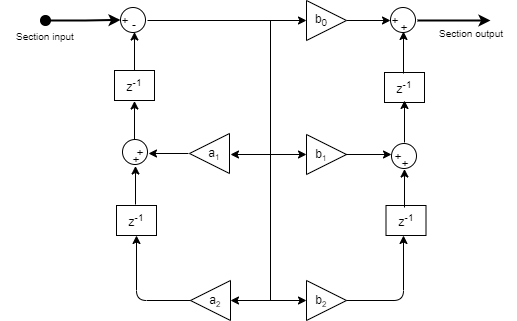
These diagrams show the filter structures supported by the second-order section filter.
Direct Form I
This is the structure of each section in the filter when you set the filter structure toDirect form I.

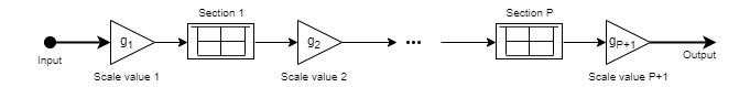
This is the structure of the filter with P sections when you specify scale values [_g_1,_g_2, …,_g_P+1].
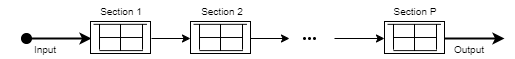
This is the structure of the filter when you do not specify scale values.
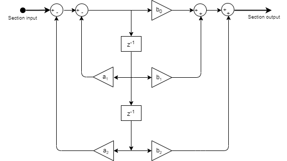
Direct Form I Transposed
This is the structure of each section in the filter when you set the filter structure toDirect form I transposed.
This is the structure of the filter with P sections when you specify scale values [_g_1,_g_2, …,_g_P+1].
This is the structure of the filter when you do not specify scale values.
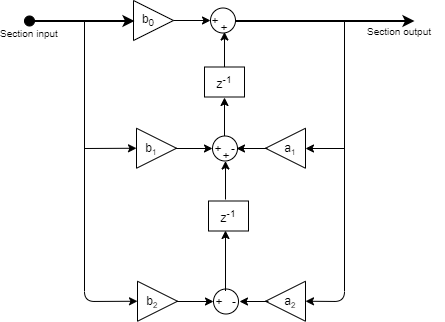
Direct Form II
This is the structure of each section in the filter when you set the filter structure toDirect form II.
This is the structure of the filter with P sections when you specify scale values [_g_1,_g_2, …,_g_P+1].
This is the structure of the filter when you do not specify scale values.
Direct Form II Transposed
This is the structure of each section in the filter when you set the filter structure toDirect form II transposed.
This is the structure of the filter with P sections when you specify scale values [_g_1,_g_2, …,_g_P+1].
This is the structure of the filter when you do not specify scale values.
Extended Capabilities
Symbolic Dimension Support
This block supports setting symbolic dimensions for simulation and for code generation. You can specify the dimension information in the block as symbols (variables). These symbols propagate throughout the model during simulation and then go into the generated code. That way, you do not need to change the dimensions in the block each time you update this information.
- The ports that support symbolic dimensions are these:
Num— The dimensions must be[P 3], wherePis the number of sections.Den— The dimensions must be[P M], whereMcan be2or3.g— The dimension must beP+1, wherePis the number of sections.
- The block supports symbolic dimensions only in the normal simulation mode.
You must have Simulink Coder™ and Embedded Coder® to use this functionality.
For more information, see Implement Symbolic Dimensions for Array Sizes in Generated Code (Embedded Coder).
Version History
Introduced in R2023b
The Second-Order Section Filter block supports setting symbolic dimensions for simulation and code generation.