External Mode Simulation by Using XCP Communication - MATLAB & Simulink (original) (raw)
In an external mode simulation, you can tune parameters in real time and monitor target application signals. Using the Run on Custom Hardware app, you can set up and run on your development computer or custom hardware external mode simulations that use an XCP communication channel.
For an external mode simulation, you:
- Build the target application on your development computer.
- Deploy the target application to the target hardware.
- Connect Simulink® to the target application that runs on the target hardware.
- Start execution of generated code on the target hardware.
Run XCP External Mode Simulation on Development Computer
Configure and run an external mode simulation that uses the XCP communication protocol. During the simulation:
- Monitor a signal by using a Scope block, a Dashboard block, and the Simulation Data Inspector.
- Tune a parameter by using a Dashboard block.
Configure Signal Monitoring and Parameter Tuning for XCP
- Create a folder for this example.
mkdir ext_mode_xcp_example
cd ext_mode_xcp_example - Open Simulink and create a simple model,
xcpExample, which contains these blocks:- Sine Wave
- Gain
- Scope
- Half Gauge
- Knob
- Double-click the Sine Wave block. Set Sample time to 0.1, and then click OK.
- Double-click the Gain block. Set Gain to 2, and then click OK.
- Connect the Sine Wave block to the Gain block and name the connection, for example,
Test Signal. - Connect the Gain block to the Scope block and name the connection, for example,
Output Signal. - Configure
Test Signalfor logging:- Select
Test Signal. - On the Signal tab, in the Monitor section, select Log Signals.
If you do not enable signal logging, you cannot streamTest Signalto the Simulation Data Inspector.
- Select
- Configure the Half Gauge block to monitor the value of
Test Signal:- Double-click the Half Gauge block.
- In the Simulink Editor, select
Test Signal. - In the Block Parameters dialog box:
- Connect the block to
Test Signal. - In the Maximum field, enter a value, for example,
1.
- Connect the block to
- Click OK.
- Configure the Knob block to tune the Amplitude parameter of the Sine Wave block:
- Double-click the Knob block.
- In the Simulink Editor, select the Sine Wave block.
- In the Block Parameters dialog box:
- Connect the block to the Amplitude parameter of the Sine Wave block.
- In the Minimum and Maximum fields, enter values, for example, 0.1 and 1 respectively.
- Click OK.
- Save the model as
xcpExample.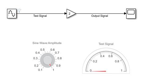
Specify Hardware and Prepare Model
- From the Apps tab on the Simulink toolstrip, in the Setup to Run on Hardware section, click Run on Custom Hardware. On the Run on Custom Hardware pop-up dialog box, click Finish.
- In the Hardware section, in the Board field, use the default
No Board. - In the Prepare gallery, under Model Configuration, click Hardware Settings. The Configuration Parameters dialog box opens, displaying Hardware Implementation settings that are determined by the system target file.
- On the Solver pane, in the Type field, specify
Fixed-step. Then, under Solver details, in the Fixed-step size (fundamental sample time) field, specify 0.1. - On the > pane, set Default parameter behavior to
Tunable. - On the > pane, select the External mode check box. Then set Transport layer to
XCP on TCP/IP. SelectingXCP on TCP/IPautomatically specifiesext_xcpfor MEX-file name, selects the Automatically allocate static memory check box, and enables Maximum duration. For this example, use the default value of Maximum duration. - If System target file is
ert.tlc, on the > pane select the Generate an example main program check box, and set Target operating system toBareBoardExample.The code generator uses the documented APIs of the external mode abstraction layer that are available in_`matlabroot`_\toolbox\coder\xcp\src\target\ext_mode\include\ext_mode.hto create an example that shows how you can provide XCP external mode target connectivity for a bare board that does not run an operating system. - Click OK to apply the changes and close the dialog box.
On the Hardware tab, the Connection field displaysIP: "localhost" – Port:17725. The connection between Simulink and your development computer was specified in step c when you setTransport layer toXCP on TCP/IP.
- On the Solver pane, in the Type field, specify
- Save the model.
Build and Run Target Application
In the Run on Hardware section:
- To specify a nondefault value for the simulation stop time, in theStop Time field, specify your value, for example,
inf. - Click Monitor & Tune
 to start the process. The software:
 - Builds the target application files including the executable file. The debugging symbols for signals are created as part of the executable file or in a separate file, depending on the configuration of Code Generation. To learn more about different configurations for Code Generation, see Approaches for Building Code Generated from Simulink Models.
- Deploys the target application as a separate process on your development computer.
- Connects Simulink to the target application.
- Starts the generated model code.
To perform the steps separately, click the following buttons under > , in this order: - Build for Monitoring
- Deploy
- Connect
- Start
Monitor Signal and Tune Parameter
You can monitor Test Signal through the:
- Scope block — Double-click the block.
- Simulation Data Inspector — Click the Simulation Data Inspector button. When the Simulation Data Inspector opens, select the Test Signal check box, which displays streamed data.
- Half-Gauge block.
To change the amplitude of the sine wave, rotate the pointer on theKnob block to the required value.
This table describes more ways of tuning tunable block parameters during a simulation.
| Approach | Details |
|---|---|
| Model Data Editor | To tune parameters through the Model Data Editor: On the Hardware tab of the Simulink Editor, in the Prepare section, clickTune Parameters, which opens the Model Data Editor.If you want to update multiple tunable parameters simultaneously, in the Prepare section, toggle on Hold Updates.On the Parameters tab of the Model Data Editor, in theValue column, specify new values for your tunable parameters.Toggle off Hold Updates or clickUpdate All Parameters (Ctrl+D). Simulink downloads the new values to the target application simultaneously. If Hold Updates is off, then immediately after you specify a new value, Simulink downloads the new value to the target application.For more information, see Model Data Editor. |
| Block Parameter dialog box | To tune parameters through the Block Parameter dialog box: For each block that you want to update: Double-click the block, which opens the Block Parameter dialog box.In the parameter fields, specify new parameter values.Click Apply or OK.If Hold Updates is on, toggle offHold Updates or click Update All Parameters (Ctrl+D). Simulink downloads the new values to the target application simultaneously. If Hold Updates is off, then immediately after you click Apply orOK, Simulink downloads the new block values to the target application. |
| MATLAB® workspace | If block parameters are MATLAB workspace variables: In the Command Window, assign new values to the variables.On the Hardware tab of the Simulink Editor, in the Prepare section, clickUpdate All Parameters (Ctrl+D). Simulink downloads the new values to the target application.For more information, see Create and Edit Variables. |
For more information about parameter tuning with generated code, see External Mode Simulation with TCP/IP or Serial Communication and Create Tunable Calibration Parameter in the Generated Code.
If your model contains a Stateflow® chart, you can view state activity. For more information, see Animate Stateflow Charts (Stateflow).
Stop Target Application
To stop the execution and disconnect the target application before Stop Time is reached, in the Run on Hardware section of theHardware tab, click Stop  .
.
If you want to disconnect the target application from Simulink without stopping code execution, click > > .
Triggered Signal Monitoring for XCP External Mode Simulations
For XCP external mode simulations, you can configure a trigger that starts the uploading of target application data for signal monitoring in Simulink.
 Create a simple model in a local folder.
In the Command Window, enter these commands:
% Create work folder
if mkdir('workFolder')
rmdir 'workFolder' s
mkdir('workFolder')
end
cd workFolder
open_system(new_system('myModel'));
% Add, configure, and connect blocks
add_block('simulink/Sources/Sine Wave','myModel/Signal',...
'Bias','5',...
'Amplitude','2',...
'SampleTime','0.01');
set_param('myModel/Signal','position',[140,80,180,120]);
add_block('simulink/Math Operations/Gain','myModel/Signal Gain',...
'Gain','2');
set_param('myModel/Signal Gain','position',[340,80,380,120]);
add_line('myModel','Signal/1','Signal Gain/1');
% Label signal
signal=get_param('myModel/Signal','PortHandles');
set_param(signal.Outport(1),'Name','test_signal');
% And so on
add_block('simulink/Math Operations/Product','myModel/Product');
set_param('myModel/Product','position',[540,160,580,200]);
add_line('myModel','Signal Gain/1','Product/1');
add_block('simulink/Sources/Sine Wave','myModel/Carrier',...
'Bias','5',...
'Amplitude','10',...
'Frequency','3',...
'SampleTime','0.02');
set_param('myModel/Carrier','position',[140,240,180,280]);
add_block('simulink/Math Operations/Gain','myModel/Carrier Gain');
set_param('myModel/Carrier Gain','position',[340,240,380,280]);
add_line('myModel','Carrier/1','Carrier Gain/1');
signal=get_param('myModel/Carrier','PortHandles');
set_param(signal.Outport(1),'Name','test_carrier');
add_block('simulink/Signal Attributes/Rate Transition',...
'myModel/Rate Transition');
set_param('myModel/Rate Transition','position',[440,200,480,240]);
add_line('myModel','Carrier Gain/1','Rate Transition/1');
add_line('myModel','Rate Transition/1','Product/2');
add_block('simulink/Sources/Constant','myModel/Constant',...
'Value','0');
set_param('myModel/Constant','position',[340,320,380,360]);
add_block('simulink/Logic and Bit Operations/Relational Operator',...
'myModel/Relational Operator','Operator','>=');
set_param('myModel/Relational Operator','position',[540,300,580,340]);
add_line('myModel','Carrier Gain/1','Relational Operator/1');
add_line('myModel','Constant/1','Relational Operator/2');
signal=get_param('myModel/Carrier Gain','PortHandles');
set_param(signal.Outport(1),'Name','pos_carrier');
add_block('simulink/Sinks/Scope','myModel/ScopeA');
set_param('myModel/ScopeA','position',[740,160,780,200]);
add_line('myModel','Product/1','ScopeA/1');
signal=get_param('myModel/Product','PortHandles');
set_param(signal.Outport(1),'Name','test_output');
add_block('simulink/Sinks/Scope','myModel/ScopeB');
set_param('myModel/ScopeB','position',[740,300,780,340]);
add_line('myModel','Relational Operator/1','ScopeB/1');
signal=get_param('myModel/Relational Operator','PortHandles');
set_param(signal.Outport(1),'Name','cmp_output');
% Finally, save the model
save_system('myModel');
2. In the Simulink Editor, configure these signals for logging by right-clicking each signal and then selecting :
test_signaltest_carriertest_outputcmp_output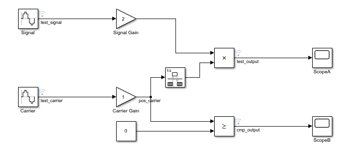
- From the Apps tab on the Simulink toolstrip, in the Setup to Run on Hardware section, click Run on Custom Hardware. On the Run on Custom Hardware pop-up dialog box, click Finish.
- In the Prepare gallery, under Model Configuration, click Hardware Settings.
- On the Solver pane, in the Type field, specify
Fixed-step. - On the > pane, select the External mode check box.
- Set Transport layer to
XCP on TCP/IP, which specifiesext_xcpfor MEX-file name. - Click OK. Then save the model.
- To open the External Signal & Triggering dialog box, from thePrepare gallery, under Signal Monitoring & Tracing, click Control Panel.
- In the Configuration section, click Signal & Triggering, which opens the External Signal & Triggering dialog box.
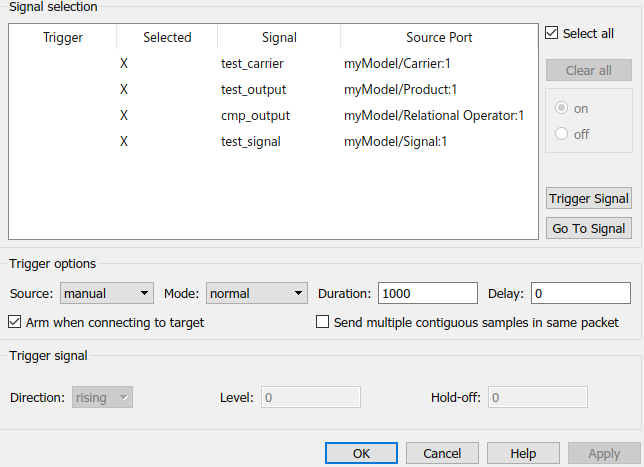
Through this dialog box, you can select signals for monitoring and configure the trigger for uploading data from the target application. For this example, use the default settings.
- The Select all check box is selected — The dialog box displays an
Xin each row of the Selected column. You can monitor all logged signals during the simulation. - Source is set to manual — The External Mode Control Panel provides manual control of data uploading, for example, the Arm Trigger button.
- The Arm when connecting to target check box is selected — When you connect Simulink to the target application, the trigger is armed.
- Click OK to close the External Signal & Triggering dialog box, then click OK to close the External Mode Control Panel.
- In the Simulink Editor, go to the Hardware tab.
- In the Stop Time field of the Run on Hardware section, specify your value, for example,
inf. - Save the model.
- Click Monitor & Tune to start the process. The software:
- Builds the target application.
- Deploys the target application as separate process on your development computer.
- Connects Simulink to the target application.
- Starts the generated model code.
To view the scope displays, double-click ScopeA andScopeB.
To monitor signals in the Simulation Data Inspector, in the Review Results section, click Data Inspector.
From the External Mode Control Panel, you can suspend or resume signal logging and monitoring. In the Connection and triggering section, clickCancel Trigger or Arm Trigger respectively.
To stop the execution of the target application and disconnect Simulink from the target environment, click Stop Real-Time Code.
For information about signal monitoring and trigger options, see XCP External Mode Control Panel and XCP External Signal & Triggering Dialog Box.
Run XCP External Mode Simulation From Command Line
You can use commands to run XCP external mode simulations. To retrieve and set the values of model parameters, use the get_param and set_param commands.
To run these commands, you must have a Simulink model open and a target application running.
- Set the model simulation mode to external mode.
set_param(gcs,'SimulationMode','external'); - Connect Simulink to the target application.
set_param(gcs,'SimulationCommand','connect') - Run generated model code.
set_param(gcs,'SimulationCommand','start'); - To tune a parameter, change its workspace variable value through a line command. For example, if a block parameter value is specified as a
Simulink.Parameterobject, assign the new value to theValueproperty. - To download the new value to the target application, update the model.
set_param(gcs,'SimulationCommand','update'); - Stop the target application and disconnect Simulink from the target environment.
set_param(gcs,'SimulationCommand','stop');
To disconnect Simulink from the target application without stopping execution of generated code, use this command:
set_param(gcs,'SimulationCommand','disconnect');
The set_param commands that use the 'SimulationCommand' argument are asynchronous. If you run the commands successively from a script, each command starts without waiting for the previous command to complete. To check that each command is complete, in the script, use the get_param command with the'SimulationStatus' argument. For example, for steps 1 to 3, specify these commands in the script:
set_param(gcs,'SimulationMode','external'); set_param(gcs,'SimulationCommand','connect');
isExternalSimulationActive = false; while ~isExternalSimulationActive simStatus = get_param(gcs, 'SimulationStatus'); isExternalSimulationActive = strcmp(simStatus, 'external'); end set_param(gcs,'SimulationCommand','start');
For more information, see Run Simulations Programmatically.
The Diagnostic Viewer displays error messages produced by the get_param and set_param commands.
This table gives parameters that you can use in get_param andset_param commands.
XCP External Mode Command-Line Parameters
| Parameter and Values | Dialog Box Equivalent | Description |
|---|---|---|
| ExtModeArmWhenConnect off, on | External Signal & Triggering: Arm when connecting to target check box | Arm the trigger as soon as the Simulink Coder™ software connects to the target. |
| ExtModeBatchMode off, on | External Mode Control Panel: Batch download check box | Enable or disable downloading of parameters in batch mode. |
| ExtModeConnected off, on | External Mode Control Panel: Connect/Disconnect button | Indicate the state of the connection with the target application. |
| ExtModeEnableFloating off,on | External Mode Control Panel: Enable data uploading check box | Enable or disable the arming and canceling of triggers when a connection is established with floating scopes. |
| ExtModeLogAll off, on | External Signal & Triggering: Select all check box | Upload available signals from the target to the host. |
| ExtModeSendContiguousSamples off, on | External Signal & Triggering: Send multiple contiguous samples in same packet check box | Specify XCP DAQ packed mode for streaming signals to Simulink. Target application sends samples from multiple time steps in a packet. ExtModeTrigDuration determines number of samples sent in the packet. |
| ExtModeTrigDelay integer (0) | External Signal & Triggering: Delay text field | Specify the amount of time (expressed in base rate steps) that elapses between a trigger occurrence and the start of data collection. |
| ExtModeTrigDirection character vector - rising,falling, either | External Signal & Triggering: Direction menu | Specify the direction in which the signal must be traveling when it crosses the threshold value. |
| ExtModeTrigDuration integer (1000) | External Signal & Triggering: Duration text field | Specify the number of base rate steps for which external mode logs data after a trigger event.IfExtModeSendContiguousSamples is on, the number of samples sent in a packet from the target application to Simulink is equal to:ExtModeTrigDuration/nwheren = (base rate)/(sample rate)Forn=1, number of samples sent in a packet is exactlyExtModeTrigDuration value. For subrates in multirate models, number of samples sent in a packet is rounded down to the nearest integer. The target application discards buffer samples that are not sent to Simulink. |
| ExtModeTrigHoldOff integer (0) | External Signal & Triggering: Hold-off text field | Specify the base rate steps between when a trigger event terminates and the trigger is rearmed. |
| ExtModeTrigLevel integer (0) | External Signal & Triggering: Level text field | Specify the threshold value the trigger signal must cross to fire the trigger. |
| ExtModeTrigMode character vector - normal,oneshot | External Signal & Triggering: Mode menu | Specify whether the trigger is to rearm automatically after each trigger event or whether only one buffer of data is to be collected each time the trigger is armed. |
| ExtModeTrigSignalBlockPath character vector | External Signal & Triggering: In Signal selection view, select signal and then click Trigger Signal button. | Specify the path to the block that contains the output port that provides the trigger signal. |
| ExtModeTrigSignalOutputPortIndex integer | External Signal & Triggering: In Signal selection view, select signal and then click Trigger Signal button. | Specify the index of the trigger signal output port for the block specified byExtModeTrigSignalBlockPath. |
| ExtModeTrigType character vector - manual,signal | External Signal & Triggering: Source menu | Specify whether to start logging data when the trigger is armed or when a specified trigger signal satisfies trigger conditions. |
Memory Allocation for Communication Buffers During XCP External Mode Simulation
You do not have to manually determine memory requirements for XCP-based external mode simulations with models that, for example, stream a large amount of data to Simulink or run on low-memory target devices.
Setting Transport layer to XCP on TCP/IP or XCP on Serial enables these configuration parameters:
- Automatically allocate static memory (
ExtModeAutomaticAllocSize) - Maximum duration (
ExtModeMaxTrigDuration) — Default is 10 base-rate steps.
The software uses model information, including the Maximum duration value, to allocate memory for:
- Internal data structures used by the XCP stack
- Storage of XCP packets
If you clear the Automatically allocate static memory check box:
- Memory allocated for internal data structures is a default value.
- You can use the Static memory buffer size (
ExtModeStaticAllocSize) field to specify memory allocated for XCP packets. The default value is 1,000,000 bytes.
If insufficient memory is allocated, the external mode simulation issues an out-of-memory error when it tries to reserve memory for internal data structures or signal streaming. In this case, reselect the Automatically allocate static memory check box to enable the software to compute the amount of memory required.
If you use the target namespace to set up XCP external mode connectivity, you can control more finely the preallocation of target hardware memory by specifying values for these XCP parameters:
MaxCTOSizeMaxDTOSize
After creating the target.XCPExternalModeConnectivity object that contains the XCP external mode connectivity options, specify the XCP parameter values through properties of the associated target.XCPTransport object. For example:
extModeConnectivity = target.create('XCPExternalModeConnectivity', ...
'Name', 'External Mode Connectivity', ...
'XCP', xcpConfiguration);
extModeConnectivity.XCP.XCPTransport.MaxCTOSize = 16 extModeConnectivity.XCP.XCPTransport.MaxDTOSize = 256
LowerMaxCTOSize and MaxDTOSize values produce a preallocation of less target hardware memory.
For more information, see Customize Connectivity for XCP External Mode Simulations.
Target Application Arguments
You can run your target application with optional arguments. You can pass the optional arguments to your target application through your custom launcher implementation.
| Argument | Description |
|---|---|
| -w | Specify that the target application enters and stays in a wait state until it receives a message from Simulink.If you do not specify -w, the target application executes model code immediately. The model code runs with parameter values from the time when you built the model. |
| -tf time | Override the model parameter StopTime.Specify time in: Seconds if PurelyIntegerCode is set to'off'.Base rate steps if PurelyIntegerCode is set to'on'.-tf inf specifies that the model runs indefinitely when model code is executed. |
For external mode simulations that run on your development computer, you can specify additional [rtiostream](target-connectivity-pil-api-components.html#bru4krc-1) arguments.
| Argument | Description |
|---|---|
| -verbose_level_ | Specify verbosity level: 0 — No information 1 — Detailed information |
| -port_number_ | For XCP on TCP/IP transport layer, specify the port number of the TCP/IP server. Use an integer value between 256 and 65535. Default is 17725.For XCP on Serial transport layer, specify the serial port ID. For example:On Windows®, 'COM1' or 1 for COM1,'COM2' or 2 for COM2, and so on.On Linux®, '/dev/ttyS0', and so on. |
| -baud_value_ | For XCP on Serial transport layer, specify the baud value: 1200, 2400, 4800, 9600, 14400, 19200, 38400, 57600 (default), or 115200. |
XCP External Mode Limitations
This table describes limitations that apply to external mode simulations that use XCP communication.
| Feature | Details |
|---|---|
| Parameter updates that change model structure | You cannot change:The number of states, inputs, or outputs of a blockThe sample time or the number of sample timesThe integration algorithm for continuous systemsThe name of the model or of a blockIf you make parameter updates that change the model structure, you must rebuild the target application.You can change numerator and denominator polynomial parameters for the Transfer Fcn, Discrete Transfer Fcn, and Discrete Filter blocks if the number of states does not change.You cannot change zero entries in the State-Space,Zero-Pole, and Discrete Zero-Pole blocks in the user-specified or computed parameters, that is, the A, B, C, and D matrices obtained by a zero-pole to state-space transformation.In theState-Space block, if you specify the matrices in the controllable canonical realization, then changes to the A, B, C, and D matrices that preserve this realization and the dimensions of the matrices are allowed.If the Simulink block diagram does not match the target application, Simulink produces an error stating that the checksums do not match. The checksums take into account the top models, but not referenced models. To rebuild the target application, use the updated block diagram. |
| Signal value display | The graphical display of signal values during a simulation is not supported. For example, you cannot use the menu items , , and . For more information, see Display Signal Values in Model Diagrams. |
| Data archiving | Data Archiving features available on theExternal Mode Control Panel are not supported. You can use the Simulation Data Inspector to collect and export data. |
| Overriding signal logging settings | If you use the Signal Logging Selector to override signal logging settings, the controls to override theDecimation and Limit data points settings are not supported. |
| Subsystem signal logging | For external mode simulations, signal logging occurs in response to anevent on the target hardware. Currently, the only supported logging event is a new sample time tick. Some subsystems are enabled or disabled by control signals. For these subsystems, the software logs signal values even when the control signals for the subsystems are not enabled.For example, if signals in an Enabled Subsystem block are configured for logging, the software logs the signal values even when the control signal for the subsystem is not greater than zero. In this case, the logged values are the values the signals had when the control signal was last greater than zero.For more information about the subsystems for which this limitation applies, see Simulink Subsystem Semantics. |
| Aperiodic task and export-function signal logging | Signal logging is not supported for aperiodic tasks and export-function models. |
| Compiler debug symbol format | Your toolchain must generate debug information in one of these formats: DWARFPDB |
| Global variables | Signals, parameters, and states must be specified as global variables. The target memory locations where the variables are stored must lie in the range 0 – 4294967295. |
| Parameter structures | You cannot tune parameters that are structures. |
| Pure integer code | Pure integer code is supported. For code generation, ifPurelyIntegerCode is 'on', specifyFixedStep with a resolution that is greater than or equal to 1 microsecond. For example, specify 1.000001, but not 1.0000001.If you do not specify -tf_finalTime_ in the execution command, the target application runs the generated model code indefinitely, ignoringStopTime.If you specify -tf_finalTime_ in the execution command: The finalTime value represents base rate steps, not seconds.The maximum value for finalTime, in ticks, is MAX_int32_T. |
| Variable-size signals | Uploading of variable-size signals is not supported. |
| Address granularity | Target hardware that uses word addresses is not supported. |
| Portable word sizes | When the production target hardware is word-addressable, the generation of a host-based target application by using portable word sizes is not supported. The production target hardware must support 8-bit, 16-bit, and 32-bit native data types. |
| Scope blocks | If your model uses Scope blocks and the amount of data logged during an external mode simulation becomes very large, Simulink might slow down. Instead of Scope blocks, you can use the Simulation Data Inspector or equivalent blocks from the Dashboard library. For more information, see Decide How to Visualize Simulation Data. |
| Scope and Floating Scope blocks, and Scope Viewer | Some signal data types are not supported. The simulation produces a warning. |
| Floating Scope blocks and Scope Viewer | You cannot use Floating Scope blocks and Scope Viewers to monitor signals in referenced models during external mode simulations. To monitor referenced model signals, enable signal logging and use the Simulation Data Inspector. |
| Scope and Display blocks in referenced models | In a model hierarchy, if the top model runs in external mode, blocks for viewing signals do not provide displays in referenced models. To monitor signals in a referenced model, enable signal logging and use the Simulation Data Inspector. |
| Scope and Display blocks connected to Simulink message blocks | During external mode simulations, Scope andDisplay blocks connected to Simulink message blocks do not provide displays.To visualize messages, use the Simulation Data Inspector or Dashboard blocks. |
| Nonzero simulation start time | Nonzero simulation start times are not supported. Use the default value for > , 0.0. |
| Intermediate step values | Some Simulink blocks can generate multiple values in a simulation time step. For example: A Simulink Function or Function-Call Subsystem block that is invoked multiple times in a time step.Iterator subsystem blocks that execute multiple times in a time step.For each time step in an external mode simulation, Simulink uploads from the target application only the final values of such blocks. Simulink does not upload the intermediate values generated during the step. |
| Service code interface | Using XCP communication for tuning parameters and monitoring signals as generated code executes in a target environment is not supported for code generated from component models configured with an ERT-based system target file and service code interface. |
| File-scoped data | File-scoped data is not supported. For example, data items to which you apply the built-in custom storage class FileScope. The simulation produces a warning.For more information about theFileScope storage class, see Choose Storage Class for Controlling Data Representation in Generated Code. |
| Row-major code generation | Code generated with the row-major format is not supported. |
| Concurrent execution | On Windows and Linux computers, concurrent execution is supported.On Mac computers, concurrent execution using the native threads example is not supported. If the External mode and Allow tasks to execute concurrently on target check boxes are selected, you cannot build the target application unless you are using a target hardware support package that supports concurrent execution for external mode simulations.On a Windows computer, at run time, the base sample time in the target application is quantized to the nearest multiple of the system timer interrupt interval (usually 15.625 ms). Sampling subrates are the expected multiples of the base sample rate. Logged timestamps in the Simulation Data Inspector (SDI) correspond to simulation times rather than wall-clock times. As an example, this table shows the step times for a Simulink model that has a base sample time of 10 ms and a subrate sample time of 20 ms.Base RateSubrateStep Wall-Clock Time (ms) Logged Timestamp (ms)StepWall-Clock Time (ms)Logged Timestamp (ms)0000001 15.625 10 2 31.250 20 1 31.250 203 46.875 30 4 62.500 40 2 62.500 40 |
| Simulation data export | You can export logged signal and top-model output data to the MATLAB workspace: For logged signal data, select the Signal logging check box.For top-model output data, select the Output check box and, from the Format list, selectDataset.If you want to export the data to a MAT file instead of the MATLAB workspace, also select the Log Dataset data to file check box.The export of simulation state data is not supported.Saving the simulation output as a single object is not supported. The simulation produces a warning. |
See Also
Topics
- External Mode Simulations for Parameter Tuning, Signal Monitoring, and Code Execution Profiling
- Mark Signals for Logging
- Set Up External Mode Connectivity Between Simulink and Target Hardware
- Customize XCP Server Software
- Perform XCP Operations on Deployed Simulink Model (Vehicle Network Toolbox)
- Simulation Data Inspector