Generate Code and Simulate Models Programmatically with Project - MATLAB & Simulink (original) (raw)
This example shows how to use the Project API to create a new project and automate project tasks for manipulating files. It covers how to programmatically create a blank project, add files and folders, set up the project path, define project shortcuts, generate code, and simulate the harness model.
Project helps you organize large designs by managing and sharing files and settings, finding required files, and interacting with source control.
Manage a Model-Based Design Project
The example models provide a controller that positions a camera fixed to a DC motor that tracks a green ball.
The MBD approach leads to modeling the controller operations:
- Model plant: The plant is a DC motor that rotates to reposition the camera.
- Model controller: The design uses a PID controller with feedback on angular position for positioning the DC motor.
- Model high-level ball tracking scheduler: The scheduler checks for validity of the position of the green ball and the saturation of the reference angle. The scheduler handles the instances of no ball on the screen to track.
The design and Project have the following folders.
Plant -- The plant provides:
- Models with continuous-time dynamic systems that use basic Simulink® blocks.
- Models with linear time invariant (LTI) systems that use the LTI system block.
- Import and export of simulation data to and from the workspace
- Loading of parameters into the base workspace that use data dictionary and model callbacks.
Controller -- The controller provides:
- Models with discrete-time dynamic systems that use basic Simulink blocks.
- Models with discrete-time dynamic systems that use the PID Controller Block.
- Enforcement of signal saturation that use a PWM Conversion subsystem.
Ball Tracking -- The ball tracking provides:
- The basic ball tracking algorithm.
- The terminator and ground blocks as placeholders.
- A hybrid controller that generates motor reference angles using Stateflow®.
Harnesses -- The harnesses provide top-level simulation of the full system.
Create a Blank Project and Add Files
1. Create a blank project. On the Home tab, click New > Project > Blank Project.
Alternatively, create this project and use currentProject to get a project object to manipulate the project from the Command Window:
exampleDir = pwd; matlab.project.createProject('modelBasedDesignCodeGenProject'); proj_modelBasedDesignCodeGen = currentProject;
2. Copy the example files to folders within the Project.
Alternatively, in the Command Window, type:
copyfile(fullfile(exampleDir,'slproject_codegen_demo'), ... fullfile(pwd),'f');
3. Add existing files to the project:
- Click the Project Files View button and select All files View.
- Select the folders
ball_tracking,controller,harnesses,plant, andutilities, right-click the icon for one of the folders, and select Add Folder to Project (Including Child Files).
Alternatively, add these files to the project programmatically from the Command Window:
addFolderIncludingChildFiles(proj_modelBasedDesignCodeGen,'ball_tracking'); addPath(proj_modelBasedDesignCodeGen,'ball_tracking'); addFolderIncludingChildFiles(proj_modelBasedDesignCodeGen,'controller'); addPath(proj_modelBasedDesignCodeGen,'controller'); addFolderIncludingChildFiles(proj_modelBasedDesignCodeGen,'harnesses'); addPath(proj_modelBasedDesignCodeGen,'harnesses'); addFolderIncludingChildFiles(proj_modelBasedDesignCodeGen,'plant'); addPath(proj_modelBasedDesignCodeGen,'plant'); addFolderIncludingChildFiles(proj_modelBasedDesignCodeGen,'utilities'); addPath(proj_modelBasedDesignCodeGen,'utilities');
4. Select the work folder, right-click the icon for one of the folders, and select Project Path > Add to the Project Path (Including Subfolders). If you choose to add this folder to the path, generated files (artifacts) from simulation and code generation are available on the project path. If you choose not to include the generated files in the project, the dependency graph does not display these files.
Alternatively, add this folder to the project path from the Command Window:
addPath(proj_modelBasedDesignCodeGen,'work');
5. To make the project more accessible, define and set properties for project shortcuts. In the Files View, select the Project tab. Open the utilities folder node.
6. Select the files clean_up_project.m, generate_controller_code.m, and set_up_project.m, right-click the icon for one of the files, and select Create Shortcut.
7. To set the current working folder, set the simulation cache folder, and run other setup scripts when you open the project:
- Select the
set_up_project.mscript. - Right-click the file.
- Select Run at Startup.
Alternatively, add this setup script to project startup from the Command Window:
addStartupFile(proj_modelBasedDesignCodeGen,fullfile(pwd,'/utilities/set_up_project.m'));
8. To restore previous settings and run other clean-up scripts when you close the project:
- Select the
clean_up_project.mscript. - Right-click the file.
- Select Run at Shutdown.
Alternatively, add the clean-up script to project shutdown programmatically from the Command Window:
addShutdownFile(proj_modelBasedDesignCodeGen,fullfile(pwd,'/utilities/clean_up_project.m'));
9. Reopen the project to run the Startup shortcut.
Alternatively, reload the project and run the set_up_project from the Command Window:
reload(proj_modelBasedDesignCodeGen); run('set_up_project');
Generate Code for the Controller from the Dependency Graph
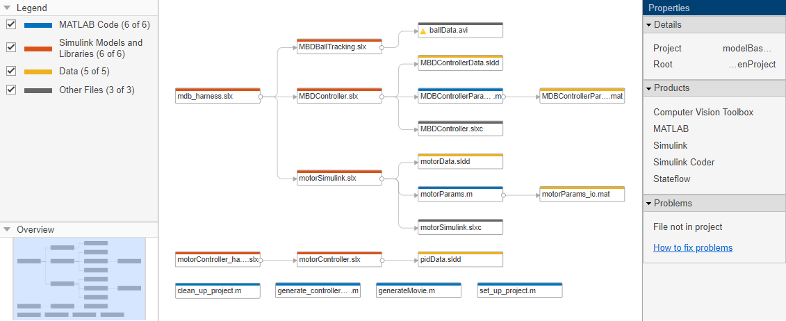
1. On the Project tab, click Dependency Analyzer to run a dependency analysis on all the files in your project.
The dependency graph displays your project structure and the files dependencies. It shows how files relate to each other. Each item in the graph represents a file, and each arrow is a dependency.
The contents of the work folder do not appear in the dependency graph. This setup simplifies the view to indicate the dependencies in model files and .m script file.
a. Examine the Properties pane on the right for useful information about your project, such as required products and problem files.
b. Use the Zoom In button to zoom into the dependencies map. Use arrow keys or click-drag with the mouse roller wheel to move around in the map.
c. Hover over the dependency arrows to examine the dependency type. For example, the MATLAB® scripts and functions are being run by model callbacks.
2. Select the MBDController.slx model on the dependency map. Right-click the model and select Open.
3. When the model opens in Simulink, click the Build button to generate code for the model. Or, use the generate_controller_code shortcut in the project to generate code.
Alternatively, generate code for the model from the Command Window. For the sake of this example, set write permissions to MBDController.slxc then generate code for the model:
fileattrib('MBDController.slxc', '+w'); evalc('slbuild(''MBDController'')');
4. Close the project from the Project window.
Alternatively, close this project and run clean_up_project from the Command Window:
run('clean_up_project'); close(proj_modelBasedDesignCodeGen);