Get Started with MATLAB to HDL Workflow - MATLAB & Simulink (original) (raw)
This example shows how to create an HDL Coder™ project and generate code from your MATLAB® design. In this example, you:
- Create a MATLAB HDL Coder project.
- Add the design and test bench files to the project.
- Start the HDL Workflow Advisor for the MATLAB design.
- Run fixed-point conversion and HDL code generation.
FIR Filter MATLAB Design
The MATLAB design mlhdlc_sfir is a simple symmetric FIR filter.
design_name = 'mlhdlc_sfir'; testbench_name = 'mlhdlc_sfir_tb';
Review the MATLAB design.
%%%%%%%%%%%%%%%%%%%%%%%%%%%%%%%%%%%%%%%%%%%%%%%%%%%%%%%%%%%%%%%%%%%%%%%%%% % MATLAB design: Symmetric FIR Filter % % Introduction: % % We can reduce the complexity of the FIR filter by leveraging its symmetry. % Symmetry for an n-tap filter implies, coefficient h0 = coefficient hn-1, % coefficient, h1 = coefficient hn-2, etc. In this case, the number of % multipliers can be approximately halved. The key is to add the % two data values that need to be multiplied with the same coefficient % prior to performing the multiplication. % % Key Design pattern covered in this example: % (1) Filter states represented using the persistent variables % (2) Filter coefficients passed in as parameters
% Copyright 2011-2019 The MathWorks, Inc.
%#codegen
function [y_out, delayed_xout] = mlhdlc_sfir(x_in,h_in1,h_in2,h_in3,h_in4)
% Symmetric FIR Filter
% declare and initialize the delay registers persistent ud1 ud2 ud3 ud4 ud5 ud6 ud7 ud8; if isempty(ud1) ud1 = 0; ud2 = 0; ud3 = 0; ud4 = 0; ud5 = 0; ud6 = 0; ud7 = 0; ud8 = 0; end
% access the previous value of states/registers a1 = ud1 + ud8; a2 = ud2 + ud7; a3 = ud3 + ud6; a4 = ud4 + ud5;
% multiplier chain m1 = h_in1 * a1; m2 = h_in2 * a2; m3 = h_in3 * a3; m4 = h_in4 * a4;
% adder chain a5 = m1 + m2; a6 = m3 + m4;
% filtered output y_out = a5 + a6;
% delayout input signal delayed_xout = ud8;
% update the delay line ud8 = ud7; ud7 = ud6; ud6 = ud5; ud5 = ud4; ud4 = ud3; ud3 = ud2; ud2 = ud1; ud1 = x_in; end
FIR Filter MATLAB Test Bench
A MATLAB testbench mlhdlc_sfir_tb exercises the filter design.
%%%%%%%%%%%%%%%%%%%%%%%%%%%%%%%%%%%%%%%%%%%%%%%%%%%%%%%%%%%%%%%%%%%%%%%%%% % MATLAB test bench for the FIR filter %%%%%%%%%%%%%%%%%%%%%%%%%%%%%%%%%%%%%%%%%%%%%%%%%%%%%%%%%%%%%%%%%%%%%%%%%%
% Copyright 2011-2019 The MathWorks, Inc. clear mlhdlc_sfir; T = 2; dt = 0.001; N = T/dt+1; sample_time = 0:dt:T;
df = 1/dt; sample_freq = linspace(-1/2,1/2,N).*df;
% input signal with noise x_in = cos(2.pi.(sample_time).*(1+(sample_time).*75)).';
% filter coefficients h1 = -0.1339; h2 = -0.0838; h3 = 0.2026; h4 = 0.4064;
len = length(x_in); y_out = zeros(1,len); x_out = zeros(1,len);
for ii=1:len data = x_in(ii); % call to the design 'mlhdlc_sfir' that is targeted for hardware [y_out(ii), x_out(ii)] = mlhdlc_sfir(data, h1, h2, h3, h4); end
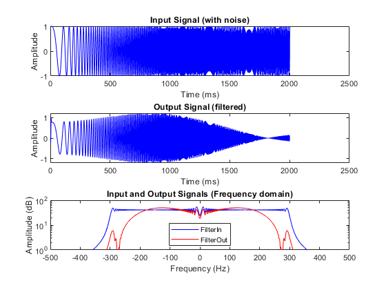
figure('Name', [mfilename, '_plot']); subplot(3,1,1); plot(1:len,x_in,'-b'); xlabel('Time (ms)')
ylabel('Amplitude') title('Input Signal (with noise)') subplot(3,1,2); plot(1:len,y_out,'-b'); xlabel('Time (ms)') ylabel('Amplitude') title('Output Signal (filtered)')
freq_fft = @(x) abs(fftshift(fft(x)));
subplot(3,1,3); semilogy(sample_freq,freq_fft(x_in),'-b'); hold on semilogy(sample_freq,freq_fft(y_out),'-r') hold off xlabel('Frequency (Hz)') ylabel('Amplitude (dB)') title('Input and Output Signals (Frequency domain)') legend({'FilterIn', 'FilterOut'}, 'Location','South') axis([-500 500 1 100])
Test the MATLAB Algorithm
To avoid run-time errors, simulate the design by using the test bench.
Create an HDL Coder Project
To create an HDL Coder project:
1. In the MATLAB Editor, in the Apps tab, select HDL Coder. Enter sfir_project as Name of the project.
To create a project from the MATLAB Command Window, run this command:
coder -hdlcoder -new sfir_project
A sfir_project.prj file is created in the current folder.
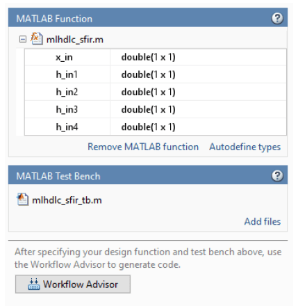
2. In the HDL Code Generation pane, in the MATLAB Function section, click Add MATLAB function and select the FIR filter MATLAB design mlhdlc_sfir. Under the MATLAB Test Bench section, click Add files and add the MATLAB test bench mlhdlc_sfir_tb.m.
3. In the HDL Code Generation pane, in the MATLAB Function section, click Autodefine types and use the recommended types for the MATLAB design. The code generator infers the input types from the MATLAB test bench.
Run Fixed-Point Conversion and HDL Code Generation
- In the HDL Code Generation pane, click the Workflow Advisor button to start the HDL Workflow Advisor.
- Right-click the HDL Code Generation task and select Run to selected task.
The code generator runs the Workflow Advisor tasks to generate HDL code for the filter design.
Translate your floating-point MATLAB design to a fixed-point design. To examine the generated fixed-point code from the floating-point design, click the Fixed-Point Conversion task. The generated fixed-point MATLAB code opens in the MATLAB editor. For details, see Floating-Point to Fixed-Point Conversion.
Generate HDL code from the fixed-point MATLAB design. By default, HDL Coder generates VHDL® code. To examine the generated HDL code, click the HDL Code Generation task, and then click the hyperlink to
mlhdlc_sfir_fixpt.vhdin the Code Generation Log window. To generate Verilog® code, in the HDL Code Generation task, select the Target tab, and set Language toVerilog. For more information and to learn how to specify code generation options, see MATLAB to HDL Code and Synthesis.