Adaptive Pipelining - MATLAB & Simulink (original) (raw)
Certain patterns or combination of blocks with registers can improve the achievable clock frequency and reduce the area usage on the FPGA boards. The adaptive pipelining optimization creates these patterns by inserting pipeline registers to the blocks in your design. To determine the optimal number of pipeline registers to insert in your design, the optimization considers the target device, target frequency, multiplier word lengths, and the settings in the HDL Block Properties. Use adaptive pipelining with:
- Clock-rate pipelining to insert pipeline registers at a faster clock-rate instead of the slower data-rate. With clock-rate pipelining, you can design your DUT at one rate and then specify an oversampling value for your design using either the Treat Simulink rates as actual hardware rates or Oversampling factor parameter. To learn more about these parameters, see Treat Simulink rates as actual hardware rates andOversampling factor.
- Resource sharing which saves area and timing because the code generator shares resources and inserts adaptive pipeline registers.
By default, the adaptive pipelining optimization is disabled on the model. In certain situations, you must enable this optimization before generating HDL code. See Design Patterns That Require Adaptive Pipelining.
Requirements
- For HDL Coder™ to insert adaptive pipelines, specify the target device. When your design has multipliers, specify the target device and the target frequency.
Note
If you use a target device that is not characterized for adaptive pipelining, the optimization uses Xilinx® Virtex®-7 whenXilinx Vivadois specified as the Synthesis Tool, and uses Intel® Stratix® V when the Synthesis Tool isAltera Quartus IIorIntel Quartus Pro. - Make sure that delay balancing is enabled for the subsystem that you want HDL Coder to insert adaptive pipelines for. If you disable delay balancing, the code generator does not insert adaptive pipelines.
- Make sure that your design does not have floating-point data types or operations.
Note
In some cases, when you have blocks inside a feedback loop, adaptive pipelining is unable to insert the required number of pipeline registers at the output. Delay balancing can then fail.
Specify Adaptive Pipelining
You can set adaptive pipelining for an entire model or, for finer control, you can set adaptive pipelining for subsystems within the top-level DUT subsystem.
Enable Adaptive Pipelining for a Model
By default, adaptive pipelining is disabled at the model level. You can enable adaptive pipelining in one of the following ways:
- In the HDL Workflow Advisor, on the > > > tab, select Adaptive pipelining.
- In the Configuration Parameters dialog box, on the > > tab, select Adaptive pipelining and click OK.
- At the command line, use the
makehdlorhdlset_paramfunction to set Adaptive pipelining toon.
hdlset_param(gcs, 'AdaptivePipelining', 'on')
Enable Adaptive Pipelining for a Subsystem
By default, subsystems in your model inherit the model-level adaptive pipelining setting. If you want HDL Coder to selectively enable adaptive pipelines for a subsystem in your model, set AdaptivePipelining toon for that subsystem.
To learn how to set adaptive pipelining for a subsystem, see Set Adaptive Pipelining For a Subsystem.
Supported Blocks
Adaptive pipelining supports these multipliers, multiply accumulate, and rate transition blocks for automatic pipeline insertion.
- Downsample
- Rate Transition
- Product
- Gain
- Multiply-Add
- Multiply-Accumulate
- MATLAB Function
Pipeline Insertion for Rate Transition and Downsample Blocks
To insert adaptive pipelines for the Rate Transition andDownsample blocks:
- Specify the target device.
- Make sure that Downsample blocks have aDownsample factor greater than two.
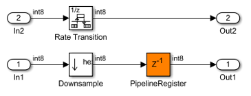
When generating code, HDL Coder inserts a pipeline register at the output port of theDownsample block. Addition of the pipeline register can avoid the bypass register logic, which saves area on the target FPGA.
This figure is the generated model for the blocks with Xilinx Virtex7 as the target FPGA device.
Pipeline Insertion for Product and Gain Blocks
To insert adaptive pipelines for these blocks:
- Specify the target device.
- Specify a target frequency greater than zero.
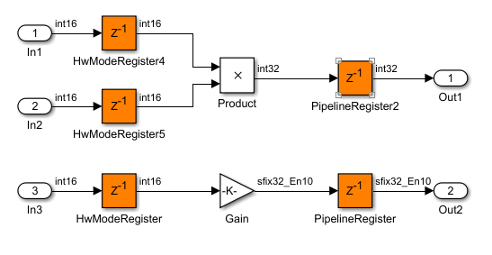
When generating code, HDL Coder inserts registers at the input and output ports of the blocks. The combination of multipliers with the registers can potentially map to DSP units on the target device.
This figure is the generated model for the Product andGain blocks with Intel Arria10 as the target FPGA device and a target frequency of 500 MHz. The inputs to the blocks are of type int16.
The pattern and number of pipeline registers that HDL Coder inserts can vary depending on the target device, target frequency, and the multiplier word lengths.
This figure is the generated model for the blocks with Xilinx Virtex7 as the target FPGA device and a target frequency of 1500 MHz. The inputs are of type int8.
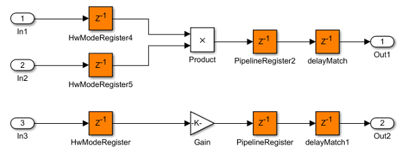
The blocks have a different number of pipeline registers at the output ports. To match the delays, HDL Coder adds a delay at the output of the Product andGain blocks.
Pipeline Insertion for Multiply-Add and Multiply-Accumulate Blocks
To insert adaptive pipelines for these blocks:
- Specify the target device.
- Specify a target frequency greater than zero.
- Use the
ParallelHDL architecture for the Multiply-Accumulate block. For an input vector of sizeN, this architecture usesNMultiply-Add blocks in series to compute the result.
Caution
The Multiply-Add block with PipelineDepth set to auto or a value greater than zero and theMultiply-Accumulate block with HDL architecture specified asParallel ignore the adaptive pipelining setting. If you specify the target FPGA device and a target frequency greater than zero, the code generator inserts pipeline registers at the inputs and outputs of the block even when adaptive pipelining is disabled.
When generating code, HDL Coder inserts registers at the input and output ports of the blocks. The combination of the blocks with the registers can potentially map to DSP units on the target device.
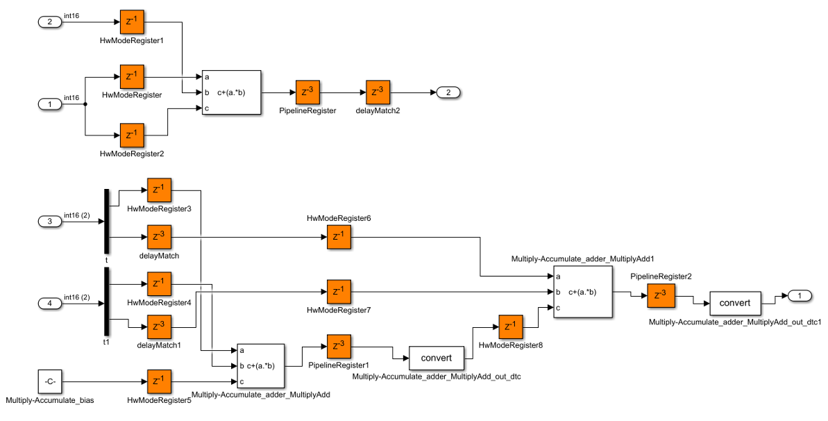
This figure is the generated model for the Multiply-Add andMultiply-Accumulate with Intel Arria10 as the target FPGA device and a target frequency of 500 MHz. The inputs to the blocks are of type int8.
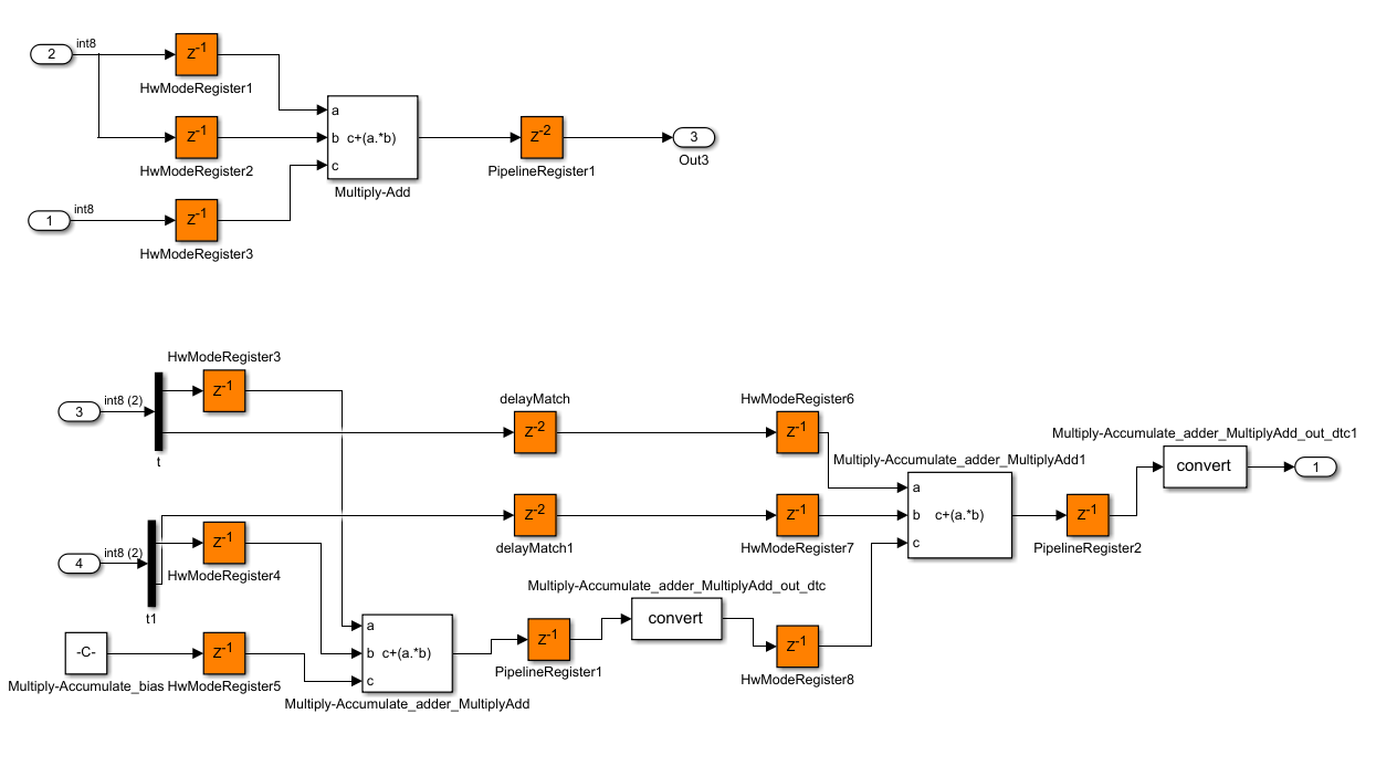
The pattern and number of pipeline registers that HDL Coder inserts can vary depending on the target device, target frequency, and the multiplier word lengths.
This figure is the generated model for the blocks with Xilinx Virtex7 as the target FPGA device and a target frequency of 1500 MHz. The inputs are of typeint16.
Pipeline Insertion for MATLAB Function Blocks
To insert adaptive pipelines for MATLAB Function blocks:
- Specify the target device.
- Specify a target frequency greater than zero.
- Set the HDL architecture for the MATLAB Function blocks to
MATLAB Datapath.
HDL Coder treats MATLAB Function blocks that have their architecture set to MATLAB Datapath like regular Subsystems. The code generator converts the MATLAB® algorithm to a Simulink® block diagram. If the Simulink diagram uses blocks that are supported by adaptive pipelining, such asProduct or Add blocks, the code generator inserts pipeline registers at the input and output ports of the blocks. The combination of multipliers with the registers can potentially map to DSP units on the target device.
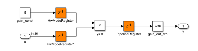
Consider a MATLAB Function block that uses the MATLAB Datapath architecture. This code is the algorithm inside theMATLAB Function block.
function y = fcn(u)
y = u*5;
This figure is the generated model for the MATLAB Function block that has Intel Arria10 as the target FPGA device and a target frequency of 500 MHz. The inputs to the blocks are of type int16. The code generator inferred the algorithm as a multiplication by a constant and inserted adaptive pipelines at the input and output.
See HDL Applications for the MATLAB Function Block.
Adaptive Pipelining Report
To see the adaptive pipelining information in the report, before you generate code for each Subsystem or model reference, enable the Code Generation report. In the Configuration Parameters dialog box, on the HDL Code Generation pane, select Generate optimization report.
When you generate HDL code, the Code Generation report opens when code generation is complete. Select the Adaptive Pipelining section of the Optimization report.
The Adaptive Pipelining report displays the status of the adaptive pipelining optimization and whether adaptive pipelines were inserted in your design.
When you enable adaptive pipelining and generate HDL code, the report displays:
- The blocks that have inserted pipeline registers. To see the pipeline registers inserted to the blocks in your design, click the link to the block.
- The number of pipeline registers inserted.
- Additional notes.
- If adaptive pipelining is not completed, the criteria that caused it to fail.
See Also
AdaptivePipelining | Clock-Rate Pipelining | Balance delays