Generate HDL Code with Annotations or Comments - MATLAB & Simulink (original) (raw)
Main Content
You can use the HDL Coder™ software to create text annotations to generated HDL code from the model annotations, text comments, or requirements in Simulink®.
Simulink Annotations
You can generate code with comments for blocks, including Inport and Outport blocks, by using Simulink annotations. When you add Simulink annotations to the model, HDL Coder renders the text from these annotations as plain text comments in generated code. The comments are generated at the same level in the model hierarchy as the subsystem that contains the annotations. The figure shows a model that has Simulink annotations for Inports, Outports, and other blocks.
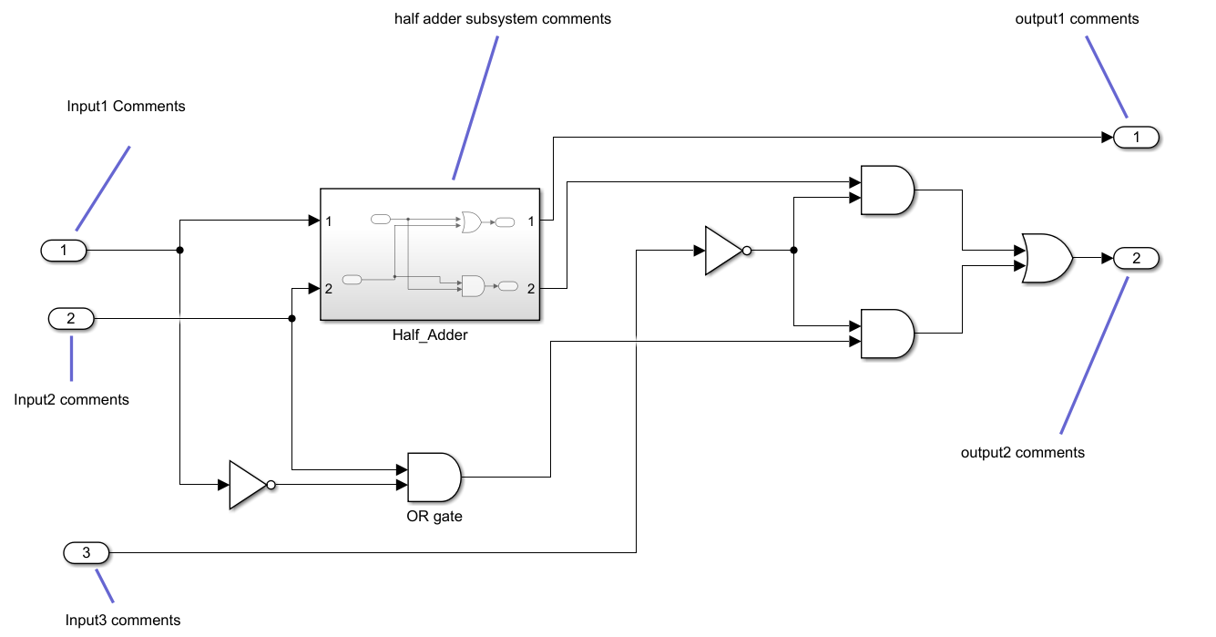
This code snippet displays the generated VHDL® code, which includes text comments for the blocks.
LIBRARY IEEE; USE IEEE.std_logic_1164.ALL; USE IEEE.numeric_std.ALL;
ENTITY Sub_Circuit IS PORT( -- Input1 Comments In1 : IN std_logic; -- Input2 comments In2 : IN std_logic; -- Input3 comments In3 : IN std_logic; -- output1 comments Out1 : OUT std_logic; -- output2 comments Out2 : OUT std_logic ); END Sub_Circuit;
ARCHITECTURE rtl OF Sub_Circuit IS
-- Component Declarations COMPONENT Half_Adder PORT( In1 : IN std_logic; In2 : IN std_logic; Out1 : OUT std_logic; Out2 : OUT std_logic ); END COMPONENT;
BEGIN -- half adder subsystem comments u_Half_Adder : Half_Adder PORT MAP( In1 => In1, In2 => In2, Out1 => Half_Adder_out1, Out2 => Half_Adder_out2 );
NOT1_out1 <= NOT In3;
AND3_out1 <= Half_Adder_out2 AND NOT1_out1;
NOT_out1 <= NOT In1;
OR_gate_out1 <= In2 AND NOT_out1;
AND5_out1 <= NOT1_out1 AND OR_gate_out1;
AND6_out1 <= AND3_out1 OR AND5_out1;
Out1 <= Half_Adder_out1;
Out2 <= AND6_out1; END rtl;
For Constant blocks, to convert annotations to comments in the HDL code, in the Configuration Parameters window:
- In the pane, in the tab, clear the Minimize intermediate signals check box.
- In the pane,set Traceability style to
Comment Based
For more information about annotations, See Annotate Models.
Signal Descriptions
When you provide a description for the signals in your Simulink model, the generated HDL code displays these descriptions as comments above the signal declaration statements. To specify a description for the signal, right-click the signal and select Properties to open the Signal Properties dialog box. Select the Documentation tab and enter a description for the signal in the Description field. For the signal description, use ASCII characters. Non-ASCII characters in the generated code may interfere with downstream synthesis and lint tools. In some cases, due to optimizations that act on the signals, the generated code may not translate all signal descriptions to HDL comments or may create replicas of HDL comments for certain signal descriptions.
Text Comments
If you enter text comments in your model by using a DocBlock block, HDL Coder renders the text from the DocBlock block in the generated code as plain text comments. The comments are generated at the same level in the model hierarchy as the subsystem that contains the DocBlock block.
Set the Document type parameter of theDocBlock block to Text. HDL Coder does not support the HTML orRTF options.
For more information about the DocBlockblock, see DocBlock.
Requirement Comments and Hyperlinks
By using Requirements Toolbox™, you can assign requirements to model elements and generate them as comments in the generated code. For example:
- Open the model
hdlcoder_simple_up_counterusing this command:
openExample("hdlcoder_simple_up_counter"); - Open the Requirements Editor (Requirements Toolbox) and create a new requirement set named
Delay_requirements.slreqx.
For more information, see Author Requirements in MATLAB or Simulink (Requirements Toolbox).
Create requirements with these details:- Custom ID: 1
- Summary: Requirement 1
- Description: Sample text 1
Similarly, create another requirement with these details: - Custom ID: 2
- Summary: Requirement 2
- Description: Sample text 2
- Open the
HDL_DUTsubsystem. - Right-click the Delay block named
Delay. From the context menu, select > . - Link the requirements. Click the New button. Set the to
Requirements 1, set toRequirements Toolbox, set toDelay_requirements.slreqx, and toRequirement 1.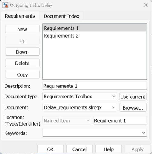
Repeat the steps 4 and 5 and link the Requirement 2 to the Subsystem. - Click Apply and OK.
- To include requirements as hyperlinked comments in the generated code, in the Configuration Parameters dialog box:
- In the pane, select Generate traceability report
- In the pane, in the tab, select Include requirements in block comments
Alternatively, if you generate code from the command line, set theTraceabilityandRequirementCommentsproperties using themakehdlfunction.
makehdl("HDL_DUT","Traceability","on","RequirementComments","on");
The generated HDL code includes comments for the Delay block andHDL_DUTsubsystem within thehdlcoder_simple_up_countermodel, containing links to the associated requirements for each block in the model.
//-------------------------------------------------------------
// Module: HDL_DUT
// Source Path: hdlcoder_simple_up_counter/HDL_DUT
// Hierarchy Level: 0
// Model version: 9.2
//
// Block requirements for /HDLDUT
// 1. Delayrequirements.slreqx:Requirement 2
//
// -------------------------------------------------------------
module HDL_DUT
(clk,
reset,
clk_enable,
count_threshold,
Enable,
ce_out,
out);
input clk;
input reset;
input clk_enable;
input [7:0] count_threshold; // uint8
input Enable;
output ce_out;
output [7:0] out; // uint8
// Block requirements for /Delay1
// 1. Delayrequirements.slreqx:Requirement 1
always @(posedge clk or posedge reset)
begin : Delay1_process
if (reset == 1'b1) begin
Delay1_out1 <= 8'b00000000;
end
else begin
if (enb) begin
Delay1_out1 <= Switch1_out1;
end
end
end
assign out = Delay1_out1;
assign ce_out = clk_enable;
endmodule // HDL_DUT