Specify Data Types Using Data Type Assistant - MATLAB & Simulink (original) (raw)
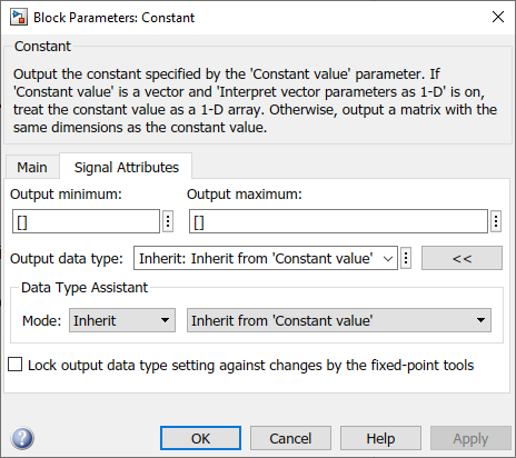
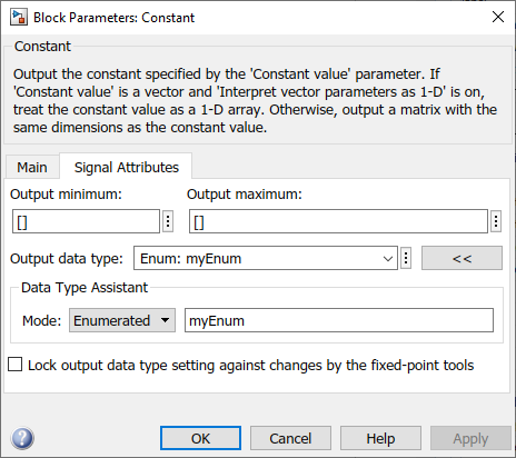
The Data Type Assistant is an interactive graphical tool that simplifies the task of specifying data types for blocks and data objects. The assistant appears on block and object dialog boxes, adjacent to parameters that provide data type control, such as theOutput data type parameter. For example, it appears on theSignal Attributes tab of the Block Parameters dialog box for theConstant block.
You can selectively show or hide the Data Type Assistant by clicking the applicable button:
- Click the Show data type assistant button
 to display the assistant.
 - Click the Hide data type assistant button
 to hide a visible assistant.
Use the Data Type Assistant to specify a data type as follows:
- From the Mode list, select the category of data type that you want to specify. In general, these options are included.
Mode Description Inherit Inheritance rules for data types Built in Built-in data types Fixed point Fixed-point data types Enumerated Enumerated data types Bus object Bus object data types Image Simulink image data types (Computer Vision Toolbox™) Value type Application-specific value types, such as wind velocity Expression Expressions that evaluate to data types The assistant changes dynamically to display different options that correspond to the selected mode. For example, setting Mode to Expressionin the Block Parameters dialog box for aConstant block updates the values in the boxes next to Output data type and Mode.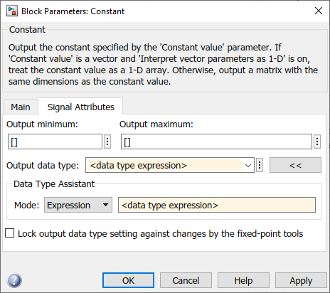
- To the right of the Mode list, select or enter a data type.
For example, suppose you designate the variablemyDataTypeas an alias for asingledata type. You create an instance of the Simulink.AliasType class and set itsBaseTypeproperty by entering these commands.
myDataType = Simulink.AliasType
myDataType.BaseType = 'single'
You can use this data type object to specify the output data type of aConstant block. Enter the data type alias name,myDataType, as the value of the expression in the assistant.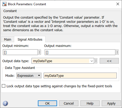
- Click OK or Apply to apply your changes.
The assistant uses the data type that you specified to populate the associated data type parameter in the block or object dialog box. For example, the Output data type parameter of the Constant block specifies the same expression that you entered using the assistant.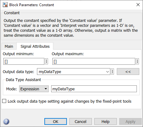
For more information about the data types that you can specify using the Data Type Assistant, see Entering Valid Data Type Values. For details about specifying fixed-point data types, see Specify Fixed-Point Data Types with the Data Type Assistant (Fixed-Point Designer).
Specifying a Fixed-Point Data Type
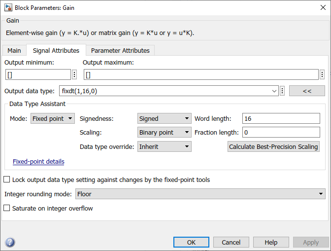
When the Data Type Assistant Mode is Fixed point, the Data Type Assistant displays fields for specifying information about your fixed-point data type. For example, the next figure shows the Block Parameters dialog box for a Gain block, with the Signal Attributes tab selected and a fixed-point data type specified.
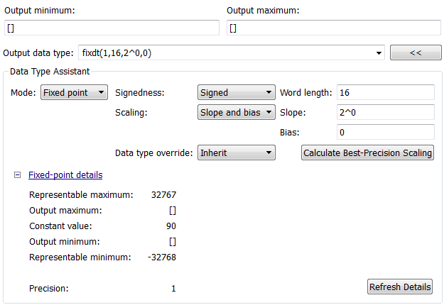
If the Scaling is Slope and bias rather than Binary point, the Data Type Assistant displays a Slope field and a Bias field rather than a Fraction length field:

You can use the Data Type Assistant to set these fixed-point properties:
Signedness
Specify whether you want the fixed-point data to be Signed or Unsigned. Signed data can represent positive and negative values, but unsigned data represents positive values only. The default setting is Signed.
Word length
Specify the bit size of the word that will hold the quantized integer. Large word sizes represent large values with greater precision than small word sizes. Word length can be any integer between 0 and 65,535. The default bit size is 16.
Scaling
Specify the method for scaling your fixed-point data to avoid overflow conditions and minimize quantization errors. The default method is Binary point scaling. You can select one of two scaling modes:
| Scaling Mode | Description |
|---|---|
| Binary point | If you select this mode, the Data Type Assistant displays the Fraction Length field, which specifies the binary point location. Binary points can be positive or negative integers. A positive integer moves the binary point left of the rightmost bit by that amount. For example, an entry of 2 sets the binary point in front of the second bit from the right. A negative integer moves the binary point further right of the rightmost bit by that amount, as in this example: The default binary point is 0. |
| Slope and bias | If you select this mode, the Data Type Assistant displays fields for entering the Slope and Bias. Slope can be any positive real number, and the default slope is 1.0. Bias can be any real number, and the default bias is 0.0. You can enter slope and bias as expressions that contain parameters you define in the MATLAB® workspace. |
Note
Use binary-point scaling whenever possible to simplify the implementation of fixed-point data in generated code. Operations with fixed-point data using binary-point scaling are performed with simple bit shifts and eliminate expensive code implementations, which are required for separate slope and bias values.
For more information about fixed-point scaling, see Scaling (Fixed-Point Designer).
Data type override
When the Mode is Built in orFixed point, you can use the Data type override option to specify whether you want this data type to inherit or ignore the data type override setting specified for its context, that is, for the block, Simulink.Signal object or Stateflow® chart in Simulink® that is using the signal. The default behavior isInherit.
| Data Type Override Mode | Description |
|---|---|
| Inherit (default) | Inherits the data type override setting from its context, that is, from the block,Simulink.Signal object or Stateflow chart in Simulink that is using the signal. |
| Off | Ignores the data type override setting of its context and uses the fixed-point data type specified for the signal. |
The ability to turn off data type override for an individual data type provides greater control over the data types in your model when you apply data type override. For example, you can use this option to ensure that data types meet the requirements of downstream blocks regardless of the data type override setting.
Calculate Best-Precision Scaling
Click this button to calculate best-precision values for both Binary point and Slope and bias scaling, based on the specified minimum and maximum values. Simulink displays the scaling values in the Fraction Length field or the Slope and Bias fields. For more information, see Constant Scaling for Best Precision (Fixed-Point Designer).
Showing Fixed-Point Details
When you specify a fixed-point data type, you can use the Fixed-point details subpane to see information about the fixed-point data type that is currently displayed in the Data Type Assistant. To see the subpane, click the expander next to Fixed-point details in the Data Type Assistant. The Fixed-point details subpane appears at the bottom of the Data Type Assistant:
The rows labeled Output minimum and Output maximum show the same values that appear in the corresponding Output minimum and Output maximum fields above the Data Type Assistant. The names of these fields may differ from those shown. For example, a fixed-point block parameter would show Parameter minimum and Parameter maximum, and the corresponding Fixed-point details rows would be labeled accordingly. See Specify Signal Ranges and Specify Minimum and Maximum Values for Block Parameters for more information.
The rows labeled Representable minimum, Representable maximum, and Precision always appear. These rows show the minimum value, maximum value, and precision that can be represented by the fixed-point data type currently displayed in the Data Type Assistant.
The values displayed by the Fixed-point details subpane do not automatically update if you click Calculate Best-Precision Scaling, or change the range limits, the values that define the fixed-point data type, or anything elsewhere in the model. To update the values shown in the Fixed-point details subpane, click Refresh Details. The Data Type Assistant then updates or recalculates all values and displays the results.
Clicking Refresh Details does not change anything in the model, it only changes the display. Click OK or Apply to put the displayed values into effect. If the value of a field cannot be known without first compiling the model, the Fixed-point details subpane shows the value as Unknown.
If any errors occur when you click Refresh Details, the Fixed-point details subpane shows an error flag on the left of the applicable row, and a description of the error on the right. For example, the next figure shows two errors:

The row labeled Output minimum shows the error Cannot evaluate because evaluating the expression MySymbol, specified in the Output minimum field, did not return an appropriate numeric value. When an expression does not evaluate successfully, the Fixed-point details subpane displays the unevaluated expression (truncating to 10 characters if necessary to save space) in place of the unavailable value.
To correct the error in this case, you would need to define MySymbol in an accessible workspace to provide an appropriate numeric value. After you clicked Refresh Details, the value of MySymbol would appear in place of its unevaluated text, and the error indicator and error description would disappear.
To correct the error shown for Output maximum, you would need to decrease Output maximum, increase Word length, or decrease Fraction length (or some combination of these changes) sufficiently to allow the fixed-point data type to represent the maximum value that it could have.
Other values relevant to a particular block can also appear in the Fixed-point details subpane. For example, on a Discrete-Time Integrator block Signal Attributes tab, the subpane can look like this:
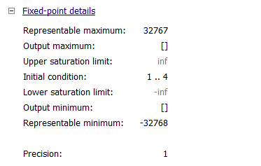
The values displayed for Upper saturation limit and Lower saturation limit are greyed out. This appearance indicates that the corresponding parameters are not currently used by the block. The greyed-out values can be ignored.
To conserve space, Initial condition displays the smallest value and the largest value in the vector or matrix, using ellipsis to represent the other values. The underlying definition of the vector or matrix is unaffected.
Lock output data type setting against changes by the fixed-point tools
Select this check box to prevent replacement of the current data type with a type that the Fixed-Point Tool or Fixed-Point Advisor chooses. For instructions on autoscaling fixed-point data, see Scaling (Fixed-Point Designer).
Specify an Enumerated Data Type
You can use the Data Type Assistant to specify an enumerated object as a data type for a block. In the Data Type Assistant, setMode to Enumerated and specify an enumerated object.
For details about enumerated data types, see Data Types.
Specify a Bus Object Data Type
You can use the Data Type Assistant to specify a Simulink.Bus object as a data type for a block or data object.
- For information on blocks that support
Simulink.Busobject data types, see Specify Bus Properties with Bus Objects. You can use the Block Parameters dialog box to access the Data Type Assistant. - For
Simulink.SignalandSimulink.Parameterobjects, use the Model Explorer to access the Data Type Assistant. - For
Simulink.BusElementobjects, use the Type Editor to access the Data Type Assistant.
In the Data Type Assistant, set Mode toBus object and specify a Simulink.Bus object.

For more information on specifying a Simulink.Bus object data type, seeSpecify Bus Properties with Bus Objects.
Specify an Image Data Type
If you have Computer Vision Toolbox, you can use the Data Type Assistant to specify aSimulink.ImageType (Computer Vision Toolbox) object as a data type for a block or data object.
In the Data Type Assistant, set Mode toImage and specify aSimulink.ImageType object.
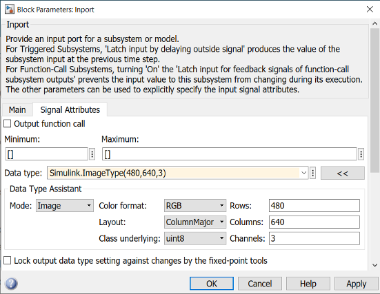
You can use the Data Type Assistant to set these image properties:
Color format
Specify the color format of the underlying image data as one of these formats:
RGBBGRBGRAGrayscale
The color format determines what each color channel of a pixel in the image represents. The default setting isRGB.
Layout
Specify the memory arrangement of the matrix data in the image asColumnMajor orRowMajor. The default setting isColumnMajor.
Class underlying
Specify the data type of the underlying image data as one of these types:
uint8uint16uint32int8int16int32singledouble
The default setting is uint8.
Rows
Specify the number of rows in the image data as a positive integer. The default setting is 480.
Columns
Specify the number of columns in the image data as a positive integer. The default setting is 640.
Channels
Specify the number of color channels or samples for each pixel in the array as one of these numbers:
134
The number of channels must correspond to the number of color channels in the color format of the image data. These values are the values ofChannels for the supported color formats.
| Color Format | Channels |
|---|---|
| Grayscale | 1 |
| RGB | 3 |
| BGR | 3 |
| BGRA | 4 |
The default setting is 3.
Specify a Value Type
You can use the Data Type Assistant to specify aSimulink.ValueType object as a data type for a block orSimulink.BusElement object.
- For information on blocks that support
ValueTypeobject data types, see Simulink.ValueType. You can use the Block Parameters dialog box to access the Data Type Assistant. - For
Simulink.BusElementobjects, use the Type Editor to access the Data Type Assistant.
In the Data Type Assistant, set Mode toValue type and specify a ValueType object.
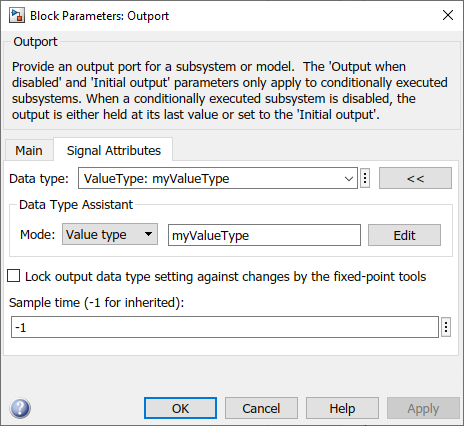
For more information on specifying value types, see Specify Common Set of Signal Properties as Value Type.
See Also
Simulink.NumericType | fixdt | Simulink.ImageType (Computer Vision Toolbox)