Update an Existing Model to Use Units - MATLAB & Simulink (original) (raw)
This example shows how to add units to an existing model. You see how to:
- Use an incremental workflow to add units to components in your model
- Integrate components that use different unit systems
- Specify units for individual elements of a bus object
- Troubleshoot unit mismatch problems
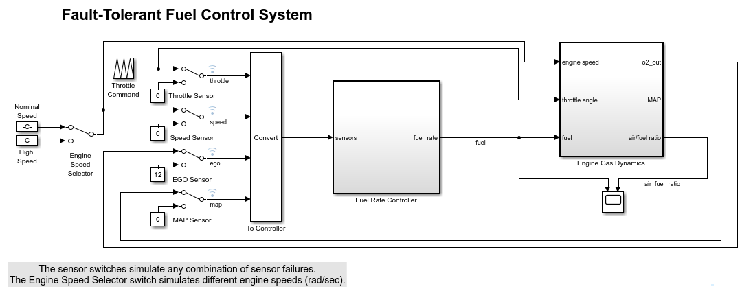
Model for Updating Units
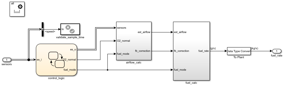
The model in the example is a fuel control system. The controller (Fuel Rate Controller) and plant (Engine Gas Dynamics) components of the model are nonvirtual subsystems. Nonvirtual subsystems have the Treat as atomic unit parameter selected. You introduce units to the plant before introducing units to the controller and connecting signals. You also specify units for the individual elements of a bus object in the model.
Open the ex_units_fuelsys model.
model=ex_units_fuelsys; open_system('ex_units_fuelsys')
Incrementally Work Through the Model to Set Units
Incrementally work through the model to set units.
For the top model, the configuration parameter determines the unit systems the model can use. For each of the plant and controller subsystems, a Unit System Configuration block determines the allowed unit systems.
| Component | Allowed Unit Systems |
|---|---|
| Top model | SI |
| Fuel Rate Controller subsystem (controller) | all |
| Engine Gas Dynamics subsystem (plant) | all |
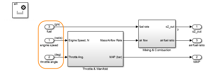
In the plant subsystem, on the Signal Attributes tab of each Inport block dialog box, set theUnit parameter to a value appropriate for the connected physical signal.
| Block | Physical Signal | Unit Parameter Setting |
|---|---|---|
| 1 | engine speed | rad/s (radians per second) |
| 2 | throttle angle | deg (degrees) |
| 3 | fuel rate | g/s (grams per second) |
To display units on ports and signals in the model, on theDebug tab, select > .
In the plant subsystem, you see units on the Inport blocks and connected signals.
Navigate back to the top model. To compile the model, pressCtrl+D, which also performs unit consistency checking.

The model displays a warning to indicate that there is a disallowed unit for the throttle angle signal. Clicking the warning icon displays a link to a Model Advisor report that gives you more detail.
The model also displays the warning at the bottom of the model editing window.
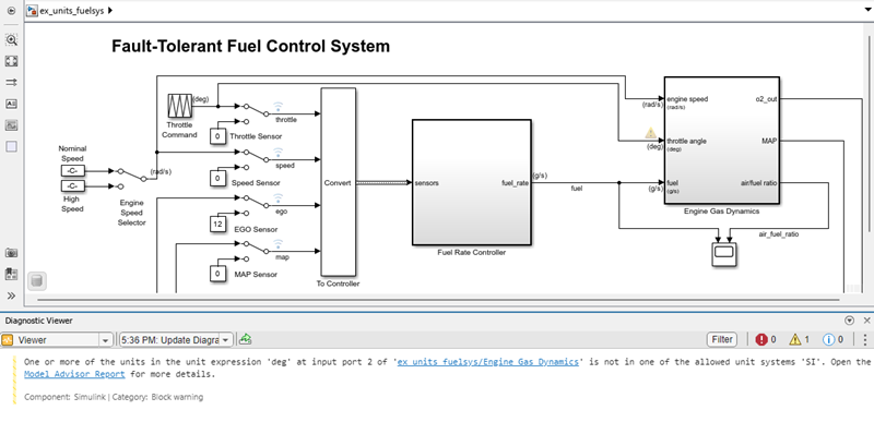
In the plant subsystem, you specified a unit of deg (degrees) for the throttle angle signal. However, the warning message indicates that degrees are not in the SI unit system. As determined by the configuration parameter, SI is the only unit system that the top model currently allows. To resolve this warning, you have two options:
- In the plant subsystem, specify a unit for the
throttle anglesignal that theSI unit system supports. For more information about supported unit systems and the units they contain, see Allowed Units. - In the top model, change the configuration parameter to expand the set of allowed unit systems.
In this case, a unit of deg for the throttle angle signal is appropriate. Instead, to resolve the warning, expand the set of allowed unit systems for the top model. Set the configuration parameter of the top model to all. To recompile the model, pressCtrl+D.
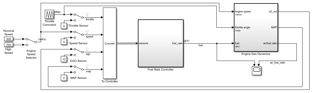
The top model no longer displays warnings.
Now that you have introduced units to the plant and successfully resolved unit inconsistency problems, you can add units to the controller. In theFuel Rate Controller subsystem, set theUnit parameter of the fuel_rate Outport block to kg/s (kilograms per second).
Navigate back to the top model. To recompile it, pressCtrl+D.
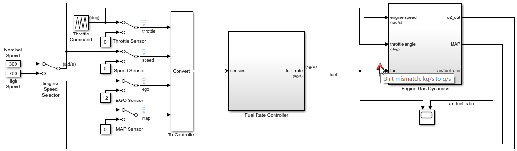
The top model now shows a warning for mismatched units between the controller and plant. To resolve this error, you can:
- Explicitly insert a Unit Conversion block between the two components.
- Select the Allow automatic unit conversions configuration parameter.
Both options convert units in the same way. A situation in which you might disallow automatic conversions and insert conversion blocks instead is when you are integrating many components in a large system model. In that case, manually inserting conversion blocks can give you an added degree of control of unit conversions in the model. Also, with a conversion block, you can control the data type of the converted signal. This is useful, for instance, when you are modeling for fixed-point precision.
In this case, to enable Simulink® to resolve the unit mismatch automatically, selectAllow automatic unit conversions. To recompile the model, press Ctrl+D.

Simulink automatically converts units between the controller and the plant. An automatic conversion icon replaces the warning.
The top model includes a Simulink.Bus object namedEngSensors that passes various sensor signals as a composite signal to the controller. To use the Type Editor to add units to individual elements of the bus object:
- On the Modeling tab, underDesign, click Type Editor.
- Set View to
Value. - In the interactive table, specify the units.
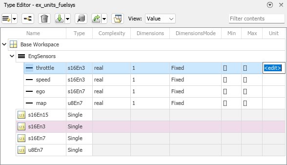
For the EngSensors bus object, set theUnit parameter of each element.
| Signal | Unit Parameter Setting |
|---|---|
| throttle | deg (degrees) |
| speed | rad/s (radians per second) |
| ego | V (volts) |
| map | bar (bars) |
To recompile the model, press Ctrl+D.
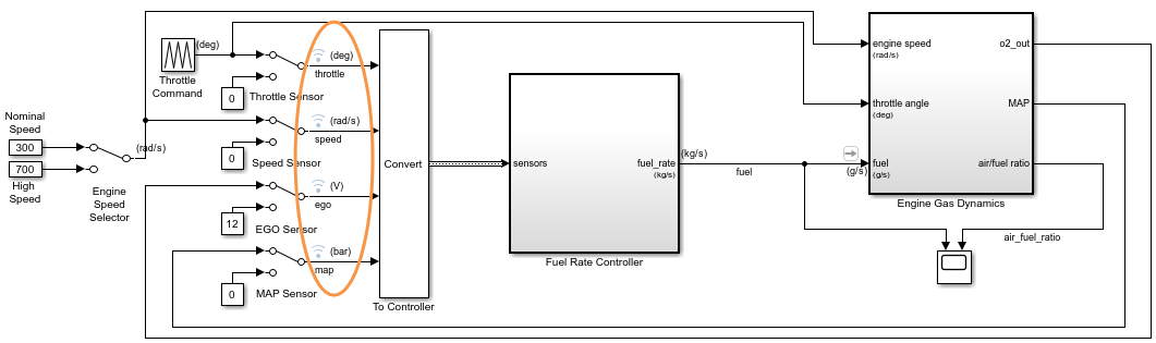
The model shows units on the individual elements of the bus object.
After you introduce units incrementally and resolve inconsistency and mismatch issues, you can simulate the model.
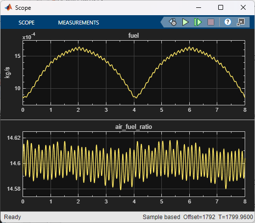
For the fuel signal that is connected to the scope, the plot window displays the associated units of kg/s as a_y_-axis label.
See Also
Unit Conversion | Unit System Configuration | Inport | In Bus Element | Outport | Out Bus Element