Model Battery Management with Custom Code - MATLAB & Simulink (original) (raw)
This example shows how to integrate custom C code into your Stateflow® chart. One use for this workflow is to model a battery state of charge (SOC) management system. Using custom C code in a Stateflow chart allows you to:
- Utilize existing algorithms that you previously developed.
- Use C code for hardware operations that are challenging to implement with Stateflow.
Battery Management
The battery management system controls power usage in battery-powered devices like vehicles and phones. Your controller monitors and regulates the SOC to:
- Maintain optimal battery health by preventing overcharge and deep discharge
- Balance power delivery with battery longevity
- Adjust power limits based on charge state
- Scale device performance to preserve battery life at low charge levels
The battery management model handles its modes of operation with three different charts.
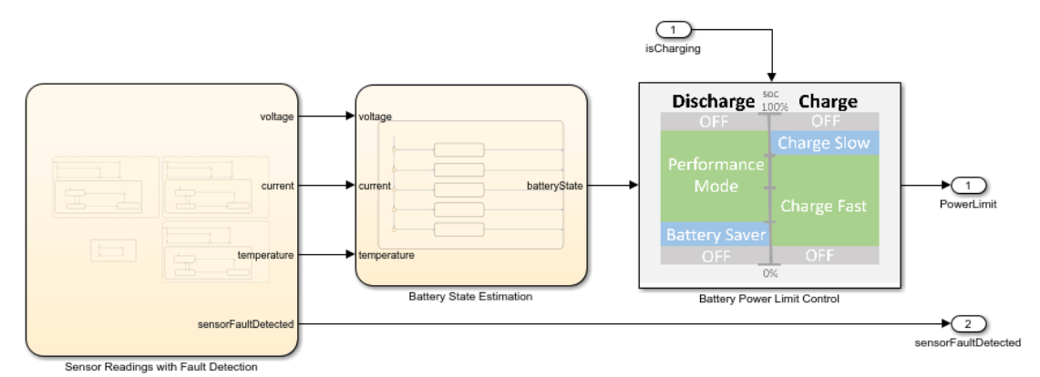
The Sensor Readings with Fault Detection chart:
- Captures voltage, current, and temperature values.
- Flags sensor faults and triggers fault handling.
- Returns valid data or fault codes to the controller.
The Battery State Estimation chart:
- Processes sensor data to calculate SOC.
- Updates battery state in real-time.
- Feeds state data to power control logic.
The Battery Power Limit Control chart:
- Sets dynamic power thresholds based on SOC.
- Enforces power limits to prevent battery damage.
- Controls charge and discharge rates.
Each chart outputs specific control signals to your battery controller, creating a complete power management solution.
With this model you can generate code and deploy that code to an embedded controller along with other control code that your system may need.

Simulate Communication with Hardware
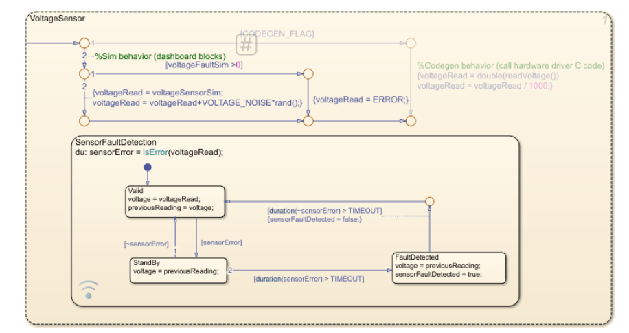
The Sensor Readings with Fault Detection chart implements three parallel states:
VoltageSensorCurrentSensorTemperatureSensor
Each state contains identical decision logic to handle both simulation and deployment modes. The CODEGEN_FLAG can be:
false, which activates simulation logic with synthesized sensor readingstrue, which executes your hardware interface code for real sensor data
For example, VoltageSensor uses variant transitions to switch between simulated voltage values and actual hardware readings based on the state of CODEGEN_FLAG.
When you use the model for simulation, the Dashboard panel allows you to control the sensor readings for the system inputs. If the calls to the battery monitor timeout, an error code of -9999 is returned from the function.
Each parallel sensor state includes SensorFaultDetection logic that:
- Stores the last valid reading when errors occur
- Monitors error duration against a preset threshold
- Triggers fault messages once threshold is exceeded
- Notifies control components of sensor failures
The example includes two custom C code files: batteryMonitorDriver.h and batteryMonitorDriver.c. These files represent the device driver code that would be used to get sensor data from the system, including battery voltage, current, and temperature and are used for code generation.
To simulate the model with the driver code:
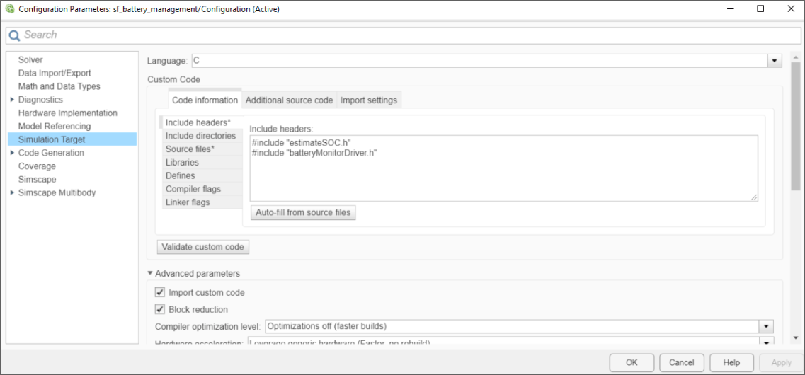
- Open the Configuration Parameters dialog box.
- In the Simulation Target pane, specify the header file and source file.
- Under Advanced parameters, select Import custom code.
For more information, see Configure Custom Code.
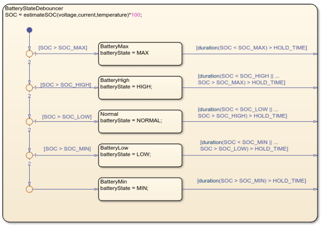
Estimate Battery State of Charge by Reusing Custom Code
To estimate the battery state of charge, the model utilizes a custom C code algorithm. The included file, estimateSOC.c, contains this code:
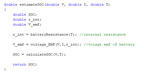
With this algorithm, you can call the C code function, rather than reimplementing it with Stateflow charts.
The estimateSOC algorithm uses debouncing to filter noise from current measurements. The Stateflow logic maps SOC values into five states:
MINLOWNORMALHIGHMAX
These ranges prevent rapid fluctuation between different control states. The exit transitions from the child states go to the edge of the parent state. When these transitions are taken, Stateflow returns to the default transition of the parent state.
Logic to Control Device State of Charge
It is easier to design this control logic with a Stateflow chart, rather than implementing the logic control through custom code. This chart implements power limit on the battery based on the estimated battery state.
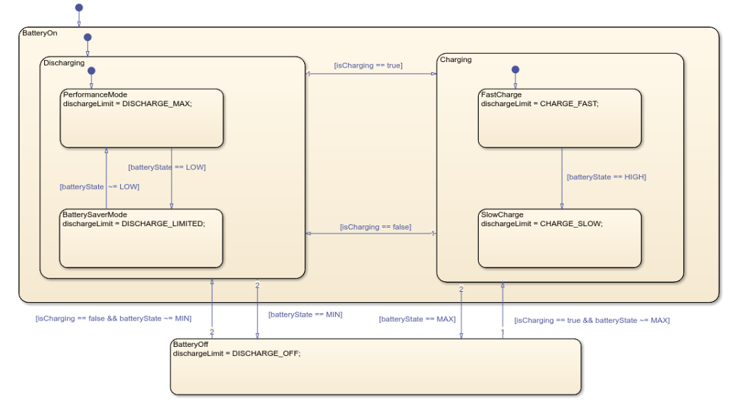
The chart represents five possible modes for power limits on the battery.
- Performance Mode: Allow high power draw when battery charge is high.
- Battery Saver Mode: Limit power draw on the battery for efficiency when charge is low.
- Off: Do not allow Power Draw when battery is at state of charge limits.
- Fast Charge: Quickly charge the battery when charge is low.
- Slow Charge: Slowly charge the battery when charge is high for battery health benefits.
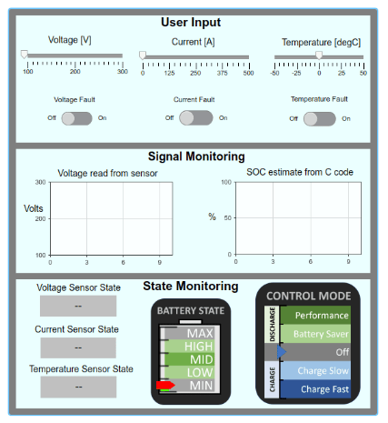
Simulate Using the Dashboard Panel
To test that the model behaves as expected, you can use the dashboard panel to simulate the voltage, current, and temperature readings. The switches allow you to simulate a sensor error to test the fault detection logic. The gauge and plot dashboard blocks are bound to the activity of Stateflow charts to visualize internal states and data. You can move and minimize the dashboard panel while navigating the model. For more information on dashboard blocks, see Control Simulations with Interactive Dashboards (Simulink).
Code Generation
Inputs into the chart Sensor Readings with Fault Detection are provided with two C code files: batteryMonitorDriver.h and batteryMonitorDriver.c. These two files represent the device driver code that would be used to get sensor data from the system, including:
- battery voltage
- current
- temperature
To use this model for code generation, the driver code must communicate with the external hardware. To enable this functionality, a variant transition using the control variable CODEGEN_FLAG allows the Stateflow chart to call the C code directly when generating code and simulate the sensor value with noise. In the command prompt, set the value of CODEGEN_FLAG to true.
For more information on Stateflow Variants and variant transitions, see Control Indicator Lamp Dimmer Using Variant Conditions.
To compile the generated code with the driver code, open the Configuration Parameters dialog box and, in the Code Generation > Custom Code pane, specify the header file and source file. For more information, see Configure Custom Code.

References
[1] Ramadass, P., B. Haran, R. E. White, and B. N. Popov. “Mathematical modeling of the capacity fade of Li-ion cells.” Journal of Power Sources. 123 (2003), pp. 230–240.
[2] Ning, G., B. Haran, and B. N. Popov. “Capacity fade study of lithium-ion batteries cycled at high discharge rates.” Journal of Power Sources. 117 (2003), pp. 160–169.