Index and Assign Values to Stateflow Structures - MATLAB & Simulink (original) (raw)
This example shows how to access and modify the contents of a Stateflow® structure or an array of Stateflow structures. A Stateflow structure is a data type that you define from a [Simulink.Bus](../../simulink/slref/simulink.bus.html) (Simulink) object. You can use Stateflow structures to bundle data of different sizes and types together into a single data object. For more information, see Access Bus Signals.
Index Substructures and Fields
To index substructures and fields of Stateflow structures, use dot notation. The first part of a name identifies the parent structure. Subsequent parts identify the children along a hierarchical path. The children can be individual fields or fields that contain other structures (also called substructures). The names of the fields of a Stateflow structure match the names of the elements of the Simulink.Bus object that defines the structure. When a field contains a vector, matrix, or array, you can access its elements by using the indexing notation supported by the action language of your chart.
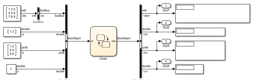
For example, the chart in this model contains an input structure (in), an output structure (out), a local structure (localbus), and a local array of structures (subBusArray).
- The chart defines the input structure
in, the output structureout, and the local structurelocalbusby using theSimulink.BusobjectBusObject. These structures have four fields:sb,a,b, andc. - The field
sbis a substructure defined from theSimulink.BusobjectSubBus. This substructure has one field calledele. - The chart defines the local array of structures
subBusArrayby using theSimulink.BusobjectSubBus. The array has size 4. Each element in the array is a structure with one field calledele.
This list illustrates expressions that combine dot notation and numeric indices based on the structure specifications for this example:
in.c— Fieldcof the input structureinin.a(1)— First element of the vector fieldaof the input structureinout.sb— Substructuresbof the output structureoutout.sb.ele— Fieldeleof the substructureout.sbout.sb.ele(2,2)— Element in the second row, second column of the fieldeleof the substructureout.sbsubBusArray(1)— First element of the array of structuressubBusArraysubBusArray(1).ele— Fieldeleof the structuresubBusArray(1)subBusArray(1).ele(3,4)— Element in the third row, fourth column of the fieldeleof structuresubBusArray(1)
Because the chart uses MATLAB® as the action language, you access the elements of the arrays in this example by using one-based indexing delimited by parentheses. In charts that use C as the action language, use zero-based indexing delimited by brackets. For more information, see Operations for Vectors and Matrices in Stateflow.
Assign Values to Structures and Fields
You can write to any Stateflow structure that has a scope other than Input. You can assign values to the entire structure, to a substructure, or to a single field.
- To assign one structure to another structure, define both structures from the same
Simulink.Busobject in the base workspace. - To assign one structure to a substructure of a different structure (or the other way around), define the structure and substructure from the same
Simulink.Busobject. - To assign a field of one structure to a field of another structure, the fields must have the same type and size. You can define the Stateflow structures from different
Simulink.Busobjects.
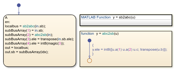
For instance, the chart in this example makes these assignments:
localbus = sb2abc(in.sb)— The structurelocalbusand the output argument of the MATLAB functionsb2abcare defined from the sameSimulink.BusobjectBusObject. The function decomposes its input into three components: a vector, a 3-by-2 matrix, and a scalar. The function returns these components as the fieldsa,b, andcof its output. For more information on this function, see Access Simulink Bus Signals in MATLAB Functions.subBusArray(1) = in.sb— The structuresubBusArray(1)and the substructurein.sbare defined from the sameSimulink.BusobjectSubBus.subBusArray(2) = abc2sb(in)— The structuresubBusArray(2)and the output argument of the graphical functionabc2sbare defined from the sameSimulink.BusobjectSubBus. The function combines the values of the fieldsa,b, andcfrom its input and rearranges them in a 3-by-3 matrix of typeint8. It returns this matrix as the fieldeleof its output.subBusArray(3).ele = transpose(in.sb.ele)— The fieldsubBusArray(3).elehas the same type and size as the result oftranspose(in.sb.ele). Both are 3-by-3 matrices of typeint8.subBusArray(4).ele = int8(magic(3))— The fieldsubBusArray(4).elehas the same type and size as the result ofint8(magic(3)). Both are 3-by-3 matrices of typeint8.out = localbus— Bothoutandlocalbusare defined from the sameSimulink.BusobjectBusObject.out.sb = subBusArray(idx)— The substructureout.sband the structuresubBusArray(idx)are defined from the sameSimulink.BusobjectSubBus.
Run the Simulation
When you simulate the example, the chart uses the values of the field sb of the input structure to populate the fields a, b, and c of the output structure. The parameter idx selects the element of the array of structures subBusArray to use as the substructure sb of the output. In this example, idx equals 2, so the chart uses the values of the fields a, b, c of the input structure to populate the substructure.
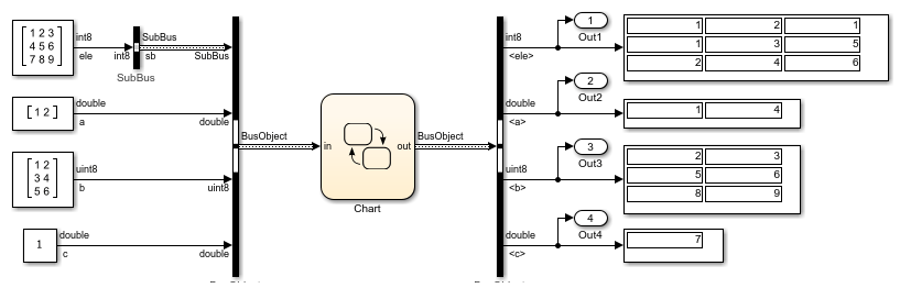
When you use other values for idx, the substructure out.sb contains the same values as in.sb, the transpose of in.sb, or a 3-by-3 magic square.
See Also
Simulink.Bus (Simulink)