Variant Components - MATLAB & Simulink (original) (raw)
Main Content
Variant components define part of an architecture model in which multiple variant choices, or variants, can exist. A variant is one of many structural or behavioral choices in a variant component. Each variant represents different design configurations for a subsystem. You can model variant choices for any component in a single architecture model. You can define variant choices as a mix of behaviors as defined by a Simulink® model, and architectures as defined by a System Composer™ architecture model. For example, a component can have three variant choices that include two alternate structural decompositions and one alternate Simulink behavior.
For example, suppose you want to simulate a model that represents a vehicle with three possible engine configurations: 4-cylinder gas, 6-cylinder gas, and 8-cylinder gas. You can use a System Composer architecture model to implement each engine model as a separate variant choice inside the Variant Component block. You can represent the 4-cylinder gas and 6-cylinder gas engine configurations using architecture models, and the 8-cylinder gas configuration using a Simulink behavior.
Use variants to quickly swap different architectural designs for a component while performing analysis. Variant controls provide the capability to swap different architecture designs by determining the active variant choice.
Variant Controls
Variant controls can operate in one of two modes: label orexpression mode.
In expression mode, System Composer chooses the active variant based on the evaluation of variant condition expressions. Each variant choice in an architecture model is associated with a variant control expression that uses a common variant control variable. The value of the variable can be changed from any workspace during runtime, thereby determining the outcome of the variant control expression and by extension, the active choice. When a variant control expression associated with a variant choice evaluates to true, System Composer activates that variant choice. When the variant control expression evaluates to false, System Composer inactivates the corresponding variant. Only one variant control expression can evaluate to true at a time.
In label mode, System Composer chooses the active variant based on variant name. The variant control is a string, and does not require you to define a variable in any workspace.
This table helps you decide which variant control mode to use for a variant component.
| Variant control mode | Usage |
|---|---|
| expression | Use expression mode to:Control the active choice from the base workspace, model workspace, or data dictionary. Each source defines a scope of visibility, which allows you to efficiently set different active choices for variants in different scopes.Allow for the optional presence of variant choices, meaning that you can configure an architecture model to ignore a variant component if none of the variant control expressions evaluate totrue during a simulation run. |
| label | Use label mode to control active choices without creating workspace variables. This variant control mode represents the simplest way of activating a variant choice. |
Create Variant Components in Label Mode
In an architecture model, a component is represented by the Variant Component block. The Variant Component block abstracts variants into a separate, hierarchical layer which is one step removed from the top architecture model layer.
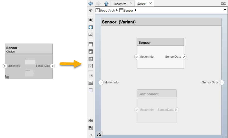
Create a variant component in label mode, and try out other related options:
- First, create a variant component block by converting a Component block to a Variant Component block. To complete the conversion, you must add variant choices to the component. To add variant choices, right-click the Variant Component block (component) and selectAdd Variant Choice from the component context menu. A Convert Component to Variant Component dialog box opens.
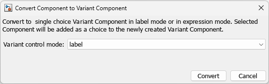
- Set the Variant control mode parameter to
labeland clickConvert. - Observe that two variant choices named Component andComponent1 are created automatically. By default, the Component choice is active.
- Modify the names of the Component andComponent1 variant choices toMotor1 and Motor2, respectively. Go up one level to the main architecture model by clicking the blue Up to Parent arrow in the toolstrip.
- Switch the active choice by selecting > > from the context menu. Note that theMotor2 variant choice is highlighted, and theMotor1 component is now grayed out.
- Navigate directly to Motor2 within the Variant Component block from the main architecture model by selecting > > from the context menu.
- View the block parameters of the component by right-clicking the
 badge on the component and selecting
Block Parameters (Subsystem). The Block Parameters: Component dialog box opens.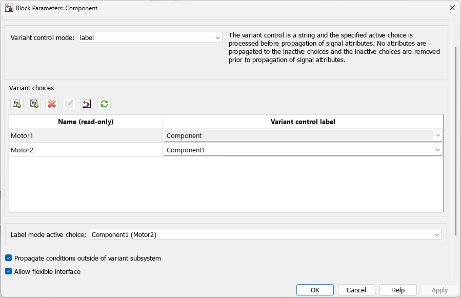
- Observe that, in the Variant choices table, the variant choice names Motor1 andMotor2 are assigned to the variant control labels,Component and Component1, respectively. The variant names listed in the Name (read-only) column are arranged in alphabetic order, rearranging the assigned variant controls in the Variant control label column accordingly.
- Identify the active choice by checking the Label mode active choice parameter. Change the active choice back toMotor1 by setting the Label mode active choice parameter to
Component (Motor1). - Select the Propagate conditions outside of variant subsystem check box to allow for propagation of the variant states to the Variant Component, so the outer component can adapt its interface accordingly. Ports that are mapped to the ports on the active choice become active. Ports that are not mapped to the ports on the inactive choice become inactive. Selecting this option ensures that the components outside of the Variant Component are aware of the active and inactive state of components within.
- Select the Allow flexible interface check box to simulate the model with variant choices that have input and output ports that differ in number from the input and output ports of the Variant Component block.
Create Variant Components in Expression Mode
Create a variant component in expression mode, and try out other related options:
- Double-click the canvas and type the block name Variant Component in the Components field. Select the Variant Component search result from the System Composer library. This block has a default of two variant choices, withComponent as the active choice.
- View the block parameters of the component by right-clicking the badge on the component and selecting
Block Parameters (Subsystem). The Block Parameters: Component dialog box opens. The Variant control mode parameter is set tolabelby default. Change it toexpression. - Choose Variant activation time as one of the following options.
Variant activation time Usage update diagram System Composer sets the active choice at the start of the model compilation stage. The inactive choices are removed from the simulation workflow. update diagram analyze all choices System Composer analyzes all variant choices to check if each choice can accept the signals connected to its inputs. It then sets the active choice late in the model compilation stage. The inactive choices are removed from the simulation workflow. - In the Variant choices table, set theVariant control expression for all variant choices to a boolean expression that can evaluate to either
trueorfalse. For example, the expressionb == 2evaluates totrueifbis then set to2in the mask, model, or base workspace. A variant control expression supports scalar variables and other data types. For more information, see Types of Variant Control Variables.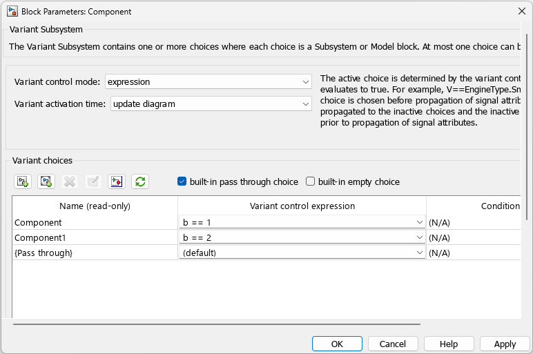
- Choose an alternative for default selection. Default selection is applicable if no variant control expression evaluates to
trueduring simulation.- Built-in empty choice — Input values to the Variant Component block do not pass on to the output ports. In other words, the inputs are terminated and the outputs are grounded. In this case, information does not pass from the variant component to other parts of the architecture model.
- Built-in passthrough choice — Input values are passed on, as they are, to the output ports without any change. Information passes on, unmodified, from the variant component to other parts of the model.