Light-directed synthesis of high-density oligonucleotide arrays using semiconductor photoresists (original) (raw)
Abstract
High-density arrays of oligonucleotide probes are proving to be powerful new tools for large-scale DNA and RNA sequence analysis. A method for constructing these arrays, using light-directed DNA synthesis with photoactivatable monomers, can currently achieve densities on the order of 106 sequences/cm2. One of the challenges facing this technology is to further increase the volume, complexity, and density of sequence information encoded in these arrays. Here we demonstrate a new approach for synthesizing DNA probe arrays that combines standard solid-phase oligonucleotide synthesis with polymeric photoresist films serving as the photoimageable component. This opens the way to exploiting high-resolution imaging materials and processes from the microelectronics industry for the fabrication of DNA probe arrays with substantially higher densities than are currently available.
Recent efforts to establish the genetic basis of human disease at the primary sequence level have created an intense demand to scale up and automate conventional methods for sequencing DNA and to develop new technologies with increased throughput and lower cost (1, 2). One promising new method for accessing genetic information on a large scale relies upon hybridization with large sets of oligonucleotide probes (3, 4, 5, 6). In addition to showing significant potential in enabling_de novo_ sequencing by hybridization, immobilized oligonucleotide arrays, or “DNA chips,” are proving to be powerful tools for monitoring gene expression (7), mapping genomic library clones (8), and resequencing genes to screen for mutations and polymorphisms (9, 10, 11, 12). As the application of this technology grows, one of the challenges will be to increase beyond present levels the volume, complexity, and density of sequence information encoded in these arrays. Further reduction in size will also facilitate the incorporation of probe arrays into the coming generation of microanalytical devices that will integrate the extraction, amplification, and analysis of nucleic acid targets from small biological samples (13, 14, 15, 16, 17).
Fabricating large probe arrays in a high-density format has presented a unique challenge (18, 19, 20, 21, 22). Recently, light-directed combinatorial synthesis (18, 19) has provided access to arrays comprised of hundreds of thousands of probes. In this approach, photolabile 5′-protecting groups are selectively removed from growing oligonucleotide chains in predefined regions of a functionalized glass support by controlled exposure to light through photolithographic masks. The spatial resolution currently achievable with this method allows arrays to be fabricated with densities on the order of 106 sequences/cm2, which corresponds to an individual feature size of about 5–10 μm. This technique, however, does not readily lend itself to further miniaturization using standard photolithographic tools. This is due to the fact that the extent of deprotection in any area of the substrate is linearly related to the amount of light received. A high contrast (≈100:1) is therefore required between illuminated, and adjacent, masked regions of the substrate to maintain a high fidelity of probe synthesis within each element of the array, and this contrast cannot be maintained as feature sizes shrink. In conventional projection lithography, contrast is limited by both stray light in the optical system, and in particular, aerial image degradation at feature sizes near the diffraction limits of the exposure tool. By comparison, photoresists used in the semiconductor industry generally exhibit a nonlinear response to illumination intensity (23, 24), which allows their routine use in generating patterned surfaces with submicron features using relatively low-contrast light images.
In this report we demonstrate the first direct application of polymeric semiconductor photoresists to the synthesis of high-density oligonucleotide arrays. Our approach was to use a patterned photoresist film as a physical barrier to “mask” selected regions of the substrate from exposure to standard chemical reagents used in oligonucleotide synthesis. Here we take advantage of the nonlinear behavior typical of semiconductor resists, such that the resist is completely removed in exposed regions and still represents an impervious layer in the unexposed regions, even with relatively low-contrast light images. With appropriate modification, this general approach should also be applicable to the construction of combinatorial arrays of peptides and other molecules.
MATERIALS AND METHODS
Glass substrates were prepared for oligonucleotide synthesis by derivatization with_N,N_-bis(hydroxyethyl)aminopropyltriethoxysilane as described (19), and then adding to the surface a protected linker, 4,4′-dimethoxytrityl (DMT)-hexaethyleneglycol-(2-cyanoethyl-_N,N_-diisopropyl)phosphoramidite (Chem-Genes, Waltham, MA), using standard DNA synthesis protocols (see below). Fluorescein phosphoramidite (Fluoreprime) and 5′-DMT-2′-deoxynucleoside phosphoramidites (thymidine, N4-isobutyryl-2′-deoxycytosine, N2-isobutyryl-2′-deoxyguanosine, N6-phenoxyacetyl-2′-deoxyadenosine) were obtained from Pharmacia. All phosphoramidite coupling reactions were performed, after the application of the resist-based imaging process, by securing the substrate to a flowcell into which standard reagents were delivered from a modified Applied Biosystems model 392 DNA synthesizer. Minor adjustments were made to the basic coupling cycle to accommodate the particular volume and mixing requirements of the flowcell, and to eliminate the detritylation step. Light-directed synthesis of oligonucleotide arrays using 5′-_O_-(α-methyl-6-nitropiperonyloxycarbonyl)-2′-deoxynucleoside phosphoramidites was performed as described (19). After synthesis, all substrates were deprotected in a 50% by volume solution 1,2-diaminoethane in ethanol for 6 hr at room temperature, rinsed with deionized water, and dried under a stream of nitrogen.
Image-wise deprotection of substrate surfaces was visualized and quantitated by fluorescence “staining,” wherein free hydroxyl groups are reacted with a fluorescein phosphoramidite using the standard coupling protocol. The pattern and intensity of surface fluorescence was imaged with a specially constructed scanning laser confocal fluorescence microscope, which employed excitation with 488-nm argon ion laser beam focused to a 2-μm spot size at the substrate surface. Emitted light was collected through confocal optics with a 530 (±15) nm bandpass filter and detected with a photomultiplier tube equipped with photon counting electronics. Relative quantitation of surface-bound fluorescein molecules was taken directly from output intensity values in photon counts per second. The relative yields of free hydroxyl groups were estimated by comparison of observed surface fluorescence intensities. Image contrast was determined as the ratio of the average fluorescence intensity in the bright (detritylated) regions over the “background” fluorescence in an adjacent dark (i.e., unexposed) region. This represented a lower limit on the true image contrast, as a result of nonspecific background fluorescence in the dark regions, for which corrections were not made.
Array hybridizations were carried out in a flowcell with the labeled oligonucleotide at 10 nM concentration in 6× standard saline phosphate/EDTA buffer (0.9 M NaCl/60 mM NaH2PO4/6 mM EDTA) at pH 7.5 for 60 min at 22°C. After removal of the oligonucleotide solution, the array was washed briefly with 6× standard saline phosphate/EDTA buffer, and then scanned. Bound oligonucleotide targets were removed from the array by incubating for several minutes at 40°C in at low-salt buffer (10 mM Tris·HCl, pH 7.5).
Image-wise surface detritylation with the XU218/SU8-photoacid resist bilayer was carried out as follows. The polyimide underlayer (XU-218, CIBA–Geigy) was applied to the substrate as a solution in anisole [7% (wt/vol), 0.45 mm filtered], spun at 3 k rpm for 45 sec, then baked at 100°C for 60 sec to remove remaining traces of anisole from the polymer film. After visual inspection for defects, the photoresist, comprised of 16.2 g of SU-8 epoxy resin (Shell Chemical, Houston, TX), 1.0 g of 9-anthracenemethanol, and 1.0 g of triphenylsulfonium hexafluoroantimonate in 83.8 g of cyclohexanone, was applied as described for the underlayer. This resulted in the deposition of uniform films of nominal 0.5-μm thickness each. The coated wafer was exposed, through a chrome-on-quartz mask in contact with the substrate, with 54 mJ/cm2 light at 365 nm from a collimated source (Optical Associates, San Jose, CA). The substrate was then baked for 60 sec at 100°C to activate the photoresist crosslinking chemistry. Features below 20 μm required a slightly higher dose (65 mJ/cm2) and a longer postexposure bake (90 sec). The substrate was spin-rinsed for 15–20 sec with cyclohexanone to develop the resist, and then air-dried. The wafer was then puddled with anisole for about 2 sec and spun at 1500 rpm under a stream of anisole for another 4–5 sec. The spinning wafer was immediately rinsed under a stream of cyclohexanone for 10 sec to remove the excess anisole and stop the polyimide etch. The patterned surface was examined by optical microscopy to ensure uniformity of the patterned areas and to verify that the undercut was no more than 2.0 μm. If defects were found at this point, the wafer was “reworked” by stripping the resist and polyimide layers as described below and repeating the processing steps to this point. Substrates were treated with 20% dichloroacetic acid-cyclohexanone for 10 min to transfer the image to the surface, rinsed with cyclohexanone, and air-dried. Immersion in dichloromethane for 2 min, followed by successive rinses with dichloromethane, 1-methyl-2-pyrrolidinone, and acetonitrile was then used to remove the resist and polyimide films from the substrate. A phosphoramidite [5′-DMT-(_N_-acyl)-2′-deoxynucleoside or Fluoreprime] was coupled to the deprotected surface as described above, and then the imaging process was repeated, as needed, for the addition of subsequent monomers to complete the sequence or array.
RESULTS AND DISCUSSION
Semiconductor microlithography consists of (i) applying a film of a polymeric photoresist onto the substrate to be patterned, (ii) image-wise exposing the photoresist film with light, (iii) “developing” the latent image by preferentially dissolving either the exposed (for a positive tone pattern) or the unexposed (negative tone) portions of the film to reveal selected regions of the underlying substrate, and (iv) transferring the image thus formed onto the substrate. Our initial strategy was to adapt this basic process, which is illustrated in Fig.1A, using readily available resist materials applied to the chemically modified surface of a glass substrate. Once the resist has been applied to the substrate and patterned, a nucleotide is added to the surface in the exposed areas using standard solid-phase oligonucleotide synthesis protocols. The glass surface is initially derivatized with hydroxyl-terminated linker molecules protected with acid-labile DMT (or “trityl”) groups. In the image-transfer step, exposed regions of the substrate are selectively deprotected (“detritylated”) by treatment with acid, revealing hydroxyl groups that are then reacted with a 5′-DMT-protected deoxynucleoside phosphoramidite. By repeating this sequence of steps in conjunction with an appropriate series of masking patterns and nucleotide additions, a large matrix of oligonucleotide sequences can be constructed in a relatively small number of steps (18, 19).
Figure 1.
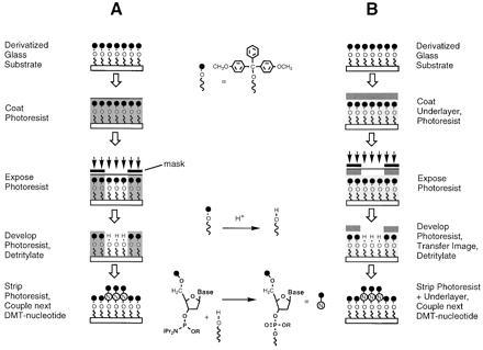
Oligonucleotide array fabrication processes using polymeric photoresists. (A) Single-layer resist process. (B) “Bilayer” process using an inert polymer underlayer to protect surface oligonucleotide chemistry.
The key issue determining the feasibility of this approach is the compatibility of the oligonucleotide chemistry with the materials and processes that are used to apply, pattern, and remove the photoresist film. Unlike typical semiconductor processing, the substrate in this case bears reactive molecules that may be susceptible to degradation during the photochemical, thermal, and chemical processes used to form the relief image. Suitable resist systems must therefore be evaluated carefully with this in mind. Clearly, to provide an effective barrier against the acid solutions used to deprotect the exposed regions of the substrate after imaging, the resist film must be impervious to the acid and exhibit good adhesion to the underlying substrate, yet remain unreactive toward the molecules on the surface. Further, resists should be imageable using near-UV or longer wavelengths (>330 nm) to avoid photochemical modification of the DNA (25).
In general, resists that were evaluated in our attempts to implement a single-layer process exhibited either poor adhesion or poor compatibility with the underlying substrate. One example was the widely used diazonapthoquinone-novolac system, a positive-tone resist comprised of diazonapthoquinone incorporated in a cresol-formaldehyde polymer matrix (26). In simple contact printing experiments with this resist, we were able to demonstrate high-contrast image-wise detritylation at a resolution of ≤4 μm. However, the alkaline conditions needed to develop this resist (aqueous OH− ≥ 0.1 M) precluded direct use in a multistep array fabrication process, due to hydrolysis of the oligonucleotide protecting groups that are used to prevent side reactions during synthesis (27).
Achieving adequate compatibility between the resist and the substrate for a single-layer process would clearly require substantial re-engineering of either an available resist system, or oligonucleotide synthesis chemistry (e.g., modification of resists to achieve milder development; more robust nucleotide protecting groups). Since our primary goal was to directly adapt available chemistry and resist processes, we decided instead to pursue an alternate scheme employing a resist bilayer (Fig. 1B). This method involved the application of an inert polymer layer to the substrate prior to the photoresist. Compared with the previous approach, the bilayer process requires additional steps to apply the underlayer and to transfer the resist image through the underlayer after development. The “underlayer” functions as both a barrier to the chemical deprotection step and as a protective layer to insulate the substrate surface from the photoresist chemistry and processing conditions. The introduction of a protective underlayer also permits somewhat greater flexibility in materials selection, since the imaging and lithographic properties of the resist can be manipulated independently of its compatibility with the substrate. This scheme requires the selection of an underlayer material with good surface adhesion and compatibility, as well as the ability to withstand the application, imaging, and stripping of the overlying resist layer.
After evaluating a number of resist-underlayer combinations, the bilayer procedure was successfully implemented using a soluble polyimide underlayer (XU–218, CIBA–Geigy), and a photoresist comprised of an epoxy resin (SU–8, Shell Chemical) and photoacid generator (triphenylsulfonium hexafluoroantimonate). The resist in this case is a negative-tone system based on photoacid-catalyzed crosslinking of the epoxy resin, wherein exposure to light renders the film insoluble (28). The crosslinked epoxy displayed excellent compatibility with the polyimide, as well as resistance toward the solvents and reagents used for DNA synthesis. Before attempting to apply this procedure to array synthesis, process steps were optimized to achieve reproducible, high-resolution patterning while maintaining compatibility with probe synthesis.
A primary factor influencing the resolution of this technique is undercutting during the wet-etching step that is used to transfer the photoresist image through the polyimide underlayer. The observed undercutting was consistent with that expected for isotropic wet etching, and was a predictable function of etch time. A nominal film thickness of 0.5 μm for both layers was chosen to achieve a balance between the degree of undercutting observed during the wet etch, and the ease with which the bilayer is later stripped from the support. Fig. 2 A and B show optical micrographs of the patterned bilayer obtained using the process to image 50- and 10-μm checkerboard patterns. Here undercutting is apparent as a distinct border around the features: the inner block is the polyimide underlayer remaining after the wet etch, and the border is due to the somewhat larger pads of overlying resist. This degree of undercutting (≤2 microns) allowed the production of 4–8 μm features reproducibly, which was sufficient for the purpose of this study. Further optimization will be needed to obtain higher resolution with this process, and preliminary experiments indicate that smaller features can be achieved by the adjustment of process parameters such as the underlayer thickness and wet-etch conditions. Additionally, mask-biasing can be used to adjust for undercutting at the exposure step, thereby providing an additional improvement in resolution.
Figure 2.
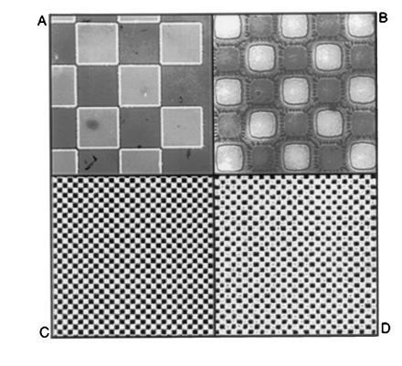
Imaging with the bilayer process. Substrates were prederivatized with a single 5′-DMT-thymidine-3′-cyanoethylphosphate monomer covalently coupled to a hexaethyleneglycol spacer before applying the patterned bilayer. (A and B) Optical micrographs of patterned bilayer film with 50- and 10-μm features, respectively. (C and D) Corresponding surface fluorescence images obtained after transferring the patterns to the substrate with dichloroacetic acid in cyclohexanone, removing the polymers, and staining with fluorescein phosphoramidite.
In the final step of transferring the image to the surface, the substrate was exposed to an acid solution to remove the DMT-protecting groups from exposed regions of the substrate. The usual acid-dichloromethane solutions could not be employed at this step, as chlorinated hydrocarbons attacked the polyimide underlayer. Instead, a 20% solution of dichloroacetic acid in cyclohexanone was used. This mixture was completely inert toward the bilayer materials, and capable of efficient DMT removal from imaged substrates, as determined by surface fluorescent staining experiments. Tests carried out with this reagent on a conventional DNA synthesizer independently verified that no significant depurination of oligonucleotides would occur as a result of its use.
After completing transfer of the image, the polymers were removed from the support with solvent, and surface detritylation was visualized and quantitated by “staining” the substrate with a fluorescein phosphoramidite using standard coupling protocols. This adds fluorescein molecules specifically and quantitatively to the unprotected surface hydroxyl groups. Immersion of the substrate in a base solution removes protecting groups from the fluorescein, allowing the pattern and intensity of surface fluorescence to be imaged with a specially constructed scanning laser confocal fluorescence microscope. Fig. 2 C and D show stained patterns of detritylation that were obtained with dichloroacetic acid/cyclohexanone after imaging 50- and 10-μm features with the resist bilayer. In a typical experiment, the observed contrast (the ratio of fluorescence intensity in exposed regions to that in nonilluminated regions) was ≈20:1. This represents a lower limit on the true image contrast, since corrections were not made for nonspecific contributions to background fluorescence in the dark regions. A small amount of distortion is apparent in the 10-μm features (Fig. 2D), due to a combination of undercutting and the resolution limits of the fluorescence microscope. Nevertheless, a clear congruence between the fluorescence and optical images of the bilayer is evident, indicating excellent fidelity in the final image-transfer step.
The overall compatibility of the bilayer process with DNA synthesis was established in a series of experiments in which it was integrated with standard nucleoside phosphoramidite coupling procedures to synthesize oligonucleotide sequences on a DMT-hexaethyleneglycol-modified substrate. Syntheses were typically followed by end-labeling the completed oligomers with fluorescein phosphoramidite after detritylating the final nucleotide in the sequence, and measuring the surface fluorescence intensity. To estimate the average stepwise synthesis efficiency obtained with the fully integrated process, fluorescence intensities were compared for series of oligonucleotide sequences ranging from one to six nucleotides in length, to obtain a value of 90(±5)% per step.
Having established the resolution capabilities of the bilayer process, and its compatibility with DNA synthesis, experiments were then performed to demonstrate that arrays of oligonucleotides synthesized by this procedure display the expected hybridization characteristics. This culminated in the synthesis of a test array comprised of the 256 decanucleotides defined by the sequence 5′-TNCNGTNCAN-3′, whereN = A, C, G, or T (Fig. 3). The combinatorial masking scheme used to synthesize the array is described elsewhere (18, 19). Since multiple exposure steps were required for this array, a relatively coarse resolution (100-μm features) was selected to simplify the mask alignment procedures. For comparison, the same array was also synthesized using photoactivatable 5′-_O_-(α-methyl-6-nitropiperonyloxycarbonyl)-nucleoside monomers as previously described (19). Hybridization of complementary fluorescein-labeled oligonucleotide “targets” was carried out in a flowcell fixed to the stage of the scanning fluorescence microscope, and hybridization to the array was determined by scanning the surface of the substrate to acquire a surface fluorescence image. The images obtained after exposing the arrays to a labeled decanucleotide sequence 5′-(fluorescein)-CTGAACGGTA-3′ are shown in Fig.4 A and B, and indicate that the two arrays have virtually identical hybridization characteristics. In both cases, the probe exhibiting the highest fluorescence intensity corresponded to the perfect complement to the target. Since these hybridizations were carried out under relatively low stringency conditions, the target also showed some binding to probes with single-base mismatches at the 3′-terminal position. To a lesser extent, mismatches were also tolerated at the 5′-penultimate position. No hybridization was observed at sites corresponding to probes that were mismatched at the internal positions. Both arrays were shown to be stable through multiple cycles of washing and rehybridization.
Figure 3.
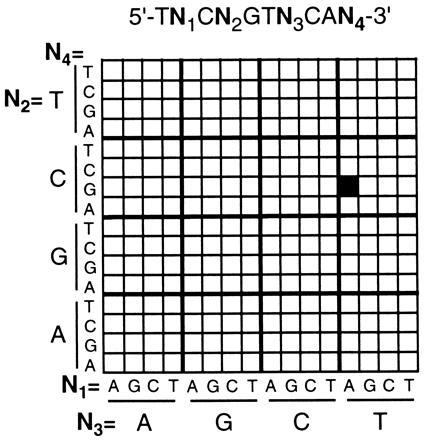
Arrangement of oligonucleotide probes in the 256-decanucleotide arrays prepared in this work. The site containing the complementary sequence 5′-TACCGTTCAG is highlighted for reference.
Figure 4.
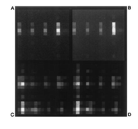
Hybridization of fluorescein-labeled oligonucleotides to the 256-decanucleotide arrays outlined in Fig. 3. Individual features are 100 μm on a side. The observed brightness at any particular location is proportional to the amount of labeled target hybridized to the probe at that site. Upper images (A and B) were acquired after hybridization of the 10-mer target 5′-fluorescein-CTGAACGGTA; and lower images (C and D) after hybridization of the 22-mer target 5′-fluorescein-ACTGGACTGAACGGTAATGCAC-3′. Images on the left (A and C) correspond to the array fabricated by the resist bilayer process with DMT-protected monomers; and images on the right (B and D), correspond to the same array fabricated with photoactivatible 5′-_O_-9α-methyl-6-nitropiperonyloxycarbonyl-protected monomers as described (19).
To access more of the test array for comparison, hybridizations were also carried out with a more complex target (5′-fluorescein-ACTGGACTGAACGGTAATGCAC-3′) that contained a number of subsequences with complete or partial complementarity to various probes in the array. A detailed discussion of the observed hybridization behavior of this target is outside the scope of this report, but here too, the array fabricated with the resist bilayer displayed essentially the same hybridization pattern and relative intensities as the control array made with photoactivatible monomers (Fig. 4 C and_D_ and Fig. 5).
Figure 5.
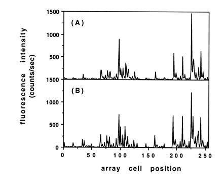
Comparison of histogram plots of the observed fluorescence intensity due to hybridization for the test arrays shown in Fig. 4 C and D. (A) Array fabricated with the resist bilayer process. (B) Array fabricated with photoactivatible monomers.
CONCLUSIONS
These results demonstrate that polymeric photoresists can be used to fabricate high-density oligonucleotide arrays with standard DMT-protected nucleoside phosphoramidites and conventional semiconductor microlithography tools. A bilayer resist process was utilized, in which an inert polymer layer protects the surface bound oligonucleotide precursors from the resist chemistry and processing. Fabrication of 8-μm features was demonstrated and higher resolution is likely with further process optimization. Test arrays prepared by this method displayed hybridization characteristics equivalent to those fabricated by previously reported methods. The primary advantages of this approach are that it provides access to higher-resolution arrays, and a commensurate increase in the volume and complexity of sequence information that can be encoded in a given area. It appears likely that an order of magnitude improvement in resolution is attainable with the photoresist approach. Work is in progress to optimize photoresist-based processes for the fabrication of oligonucleotide arrays with features on the order of ≤1 μm.
Acknowledgments
We thank S. Fodor, R. Rava, J. Winkler, D. Stern (Affymetrix), and F. Pease (Stanford University) for helpful advice and technical assistance.
Footnotes
The publication costs of this article were defrayed in part by page charge payment. This article must therefore be hereby marked “_advertisement_” in accordance with 18 U.S.C. §1734 solely to indicate this fact.
Abbreviation: DMT, 4,4′-dimethoxytrityl.
References
- 1.Hunkapillar T, Kaiser R J, Koop B F, Hood L. Science. 1991;254:59–67. doi: 10.1126/science.1925562. [DOI] [PubMed] [Google Scholar]
- 2.Lipshutz R J, Fodor S P A. Curr Opin Struct Biol. 1994;4:376–80. [Google Scholar]
- 3.Bains W, Smith G C. J Theor Biol. 1988;135:303–307. doi: 10.1016/s0022-5193(88)80246-7. [DOI] [PubMed] [Google Scholar]
- 4.Lysov Y P, Florentiev V L, Khorlyn A A, Khrapko K R, Shick V V, Mirzabekov A D. Dokl Akad Nauk SSSR. 1988;303:1508–1511. [PubMed] [Google Scholar]
- 5.Drmanac R, Labat I, Brukner I, Crkvenjakov R. Genomics. 1989;4:114–128. doi: 10.1016/0888-7543(89)90290-5. [DOI] [PubMed] [Google Scholar]
- 6.Southern E M, Maskos U, Elder J K. Genomics. 1992;13:1008–1017. doi: 10.1016/0888-7543(92)90014-j. [DOI] [PubMed] [Google Scholar]
- 7.Shena M, Shalon D, Davis R W. Science. 1995;270:467–470. doi: 10.1126/science.270.5235.467. [DOI] [PubMed] [Google Scholar]
- 8.Lipshutz R J, Morris D, Chee M, Hubbell E, Kozal M J, Shah N, Shen N, Yang R, Fodor S P A. BioTechniques. 1995;19:442–447. [PubMed] [Google Scholar]
- 9.Sapolsky R J, Lipshutz R J. Genomics. 1996;33:445–456. doi: 10.1006/geno.1996.0219. [DOI] [PubMed] [Google Scholar]
- 10.Cronin M T, Fucini R V, Kim S M, Masino R S, Wespi R M, Miyada C G. Hum Mutat. 1996;7:244–255. doi: 10.1002/(SICI)1098-1004(1996)7:3<244::AID-HUMU9>3.0.CO;2-A. [DOI] [PubMed] [Google Scholar]
- 11.Kozal M J, Shah N, Shen N, Yang R, Fucini R, Merigan T C, Richman D D, Morris M S, Hubbell E, Chee M S, Gingeras T R. Nat Med. 1996;2:753–759. doi: 10.1038/nm0796-753. [DOI] [PubMed] [Google Scholar]
- 12.Chee, M. S., Huang, X., Yang, R., Hubbell, E., Berno, A., Stern, D., Winkler, J., Lockhart, D. J., Morris, M. S. & Fodor, S. P. A. (1996) Science 610–614. [DOI] [PubMed]
- 13.Northrup M A, Ching M T, White R M, Watson R T. Digest of Technical Papers: Transducers 1993. New York: IEEE; 1993. pp. 924–926. [Google Scholar]
- 14.Effenhauser C S, Paulus A, Manz A, Widmer H M. Science. 1993;261:895–897. doi: 10.1126/science.261.5123.895. [DOI] [PubMed] [Google Scholar]
- 15.Woolley A T, Mathies R A. Proc Natl Acad Sci USA. 1994;91:11348–11352. doi: 10.1073/pnas.91.24.11348. [DOI] [PMC free article] [PubMed] [Google Scholar]
- 16.Eggers M, Ehrlich D. Hematol Pathol. 1995;9:1–15. [PubMed] [Google Scholar]
- 17.Burns M A, Mastrangelo C H, Sammarco T S, Man F P, Webster J R, Johnson B N, Foerster B, Jones D, Fields Y, Kaiser A R, Burke D T. Proc Natl Acad Sci USA. 1996;93:5556–5561. doi: 10.1073/pnas.93.11.5556. [DOI] [PMC free article] [PubMed] [Google Scholar]
- 18.Fodor S P A, Read J L, Pirrung M C, Stryer L T, Lu A, Solas D. Science. 1991;251:767–773. doi: 10.1126/science.1990438. [DOI] [PubMed] [Google Scholar]
- 19.Pease A C, Solas D, Sullivan E J, Cronin M T, Holmes C P, Fodor S P A. Proc Natl Acad Sci USA. 1994;91:5022–5026. doi: 10.1073/pnas.91.11.5022. [DOI] [PMC free article] [PubMed] [Google Scholar]
- 20.Khrapko K R, Lysov Y P, Khorlyn A A, Ivanov I B, Yerhov G M, Vasilenko S K, Florentiev V L, Mirzabekowv A D. DNA Sequencing. 1991;1:375–388. doi: 10.3109/10425179109020793. [DOI] [PubMed] [Google Scholar]
- 21.Southern E M, Maskos U. Nucleic Acids Res. 1992;20:1675–1678. doi: 10.1093/nar/20.7.1675. ; 1679–1684. [DOI] [PMC free article] [PubMed] [Google Scholar]
- 22.Blanchard A P, Kaiser R J, Hood L E. Biosens Bioelectron. 1996;11:687–690. [Google Scholar]
- 23.Willson C G. In: Introduction to Microlithography. 2nd Ed. Thompson L F, Willson C G, Bowden M J, editors. Washington, DC: Am. Chem. Soc.; 1994. pp. 139–267. [Google Scholar]
- 24.MacDonald S A, Willson C G, Frechét J M J. Acc Chem Res. 1994;27:151–158. [Google Scholar]
- 25.Cadet J, Vigny P. In: Bioorganic Photochemistry. Morrison H, editor. Vol. 1. New York: Wiley; 1990. pp. 1–272. [Google Scholar]
- 26.Reiser A. Photoreactive Polymers: The Science and Technology of Resists. New York: Wiley; 1989. pp. 178–225. [Google Scholar]
- 27.Beaucage S L, Iyer R P. Tetrahedron. 1992;48:2223–2311. [Google Scholar]
- 28.Stewart K, Hatzakis M, Shaw J M, Seeger D E, Neumann E. J Vac Sci Technol B. 1989;7:1734–1739. [Google Scholar]