dsp.FIRFilter - Static or time-varying FIR filter - MATLAB (original) (raw)
Static or time-varying FIR filter
Description
The dsp.FIRFilter System object™ filters each channel of the input using static or time-varying FIR filter implementations.
To filter each channel of the input:
- Create the
dsp.FIRFilterobject and set its properties. - Call the object with arguments, as if it were a function.
To learn more about how System objects work, see What Are System Objects?
This object supports C/C++ code generation and SIMD code generation under certain conditions. For more information, see Code Generation.
Creation
Syntax
Description
`fir` = dsp.FIRFilter returns a finite impulse response (FIR) filter object, fir, which independently filters each channel of the input over time using a specified FIR filter implementation.
`fir` = dsp.FIRFilter(`num`) returns an FIR filter System object, fir, with the Numerator property set to num.
`fir` = dsp.FIRFilter(`Name=Value`) sets properties using one or more name-value arguments. For example, to specify the initial conditions for the FIR filter as 3, setInitialConditions to 3.
Properties
Unless otherwise indicated, properties are nontunable, which means you cannot change their values after calling the object. Objects lock when you call them, and therelease function unlocks them.
If a property is tunable, you can change its value at any time.
For more information on changing property values, seeSystem Design in MATLAB Using System Objects.
Specify the filter structure. You can specify the filter structure as one of "Direct form","Direct form symmetric", "Direct form antisymmetric", "Direct form transposed", or "Lattice MA".
Specify the source of the filter coefficients as"Property" or "Input port". When you specify "Input port", the filter object updates the time-varying filter once every frame.
Dependencies
This applies when you set the Structure to "Direct form", "Direct form symmetric", "Direct form antisymmetric", or "Direct form transposed".
Specify the source of the Lattice filter coefficients as"Property" or "Input port". When you specify "Input port", the filter object updates the time-varying filter once every frame.
Dependencies
This applies when you set the Structure to "Lattice MA".
Specify the filter coefficients as a real or complex numeric row vector.
Tunable: Yes
Dependencies
This property applies when you set theNumeratorSource property to"Property", and the Structure property is set to"Direct form", "Direct form symmetric", "Direct form antisymmetric", or "Direct form transposed".
Data Types: single | double | int8 | int16 | int32 | int64 | uint8 | uint16 | uint32 | uint64
Complex Number Support: Yes
Specify the reflection coefficients of a lattice filter as a real or complex numeric row vector.
Tunable: Yes
Dependencies
This property applies when you set the Structure property to"Lattice MA", and theReflectionCoefficientsSource property to"Property".
Data Types: single | double | int8 | int16 | int32 | int64 | uint8 | uint16 | uint32 | uint64
Complex Number Support: Yes
Specify the initial conditions of the filter states. The number of states or delay elements equals the number of reflection coefficients for the lattice structure, or the number of filter coefficients–1 for the other direct form structures.
You can specify the initial conditions as a scalar, vector, or matrix. If you specify a scalar value, the FIR filter object initializes all delay elements in the filter to that value. If you specify a vector whose length equals the number of delay elements in the filter, each vector element specifies a unique initial condition for the corresponding delay element. The object applies the same vector of initial conditions to each channel of the input signal.
If you specify a vector whose length equals the product of the number of input channels and the number of delay elements in the filter, each element specifies a unique initial condition for the corresponding delay element in the corresponding channel.
If you specify a matrix with the same number of rows as the number of delay elements in the filter, and one column for each channel of the input signal, each element specifies a unique initial condition for the corresponding delay element in the corresponding channel.
Tunable: Yes
Data Types: single | double | int8 | int16 | int32 | int64 | uint8 | uint16 | uint32 | uint64
Fixed-Point Properties
Specify whether to use full precision rules. If you setFullPrecisionOverride totrue, which is the default, the object computes all internal arithmetic and output data types using full precision rules. These rules provide the most accurate fixed-point numerics. It also turns off the display of other fixed-point properties because they do not apply individually. These rules guarantee that no quantization occurs within the object. Bits are added, as needed, to ensure that no roundoff or overflow occurs. If you set FullPrecisionOverride tofalse, fixed-point data types are controlled through individual fixed-point property settings. For more information, see Full Precision for Fixed-Point System Objects.
Specify the rounding method.
Dependencies
This property applies only if the object is not in full precision mode.
Specify the overflow action as "Wrap" or"Saturate".
Dependencies
This property applies only if the object is not in full precision mode.
Specify the coefficients fixed-point data type as"Same word length as input" or"Custom".
Dependencies
This property applies when you set theNumeratorSource property to"Property".
Specify the coefficients fixed-point type as a signed or unsigned numerictype (Fixed-Point Designer) object.
Dependencies
This property applies when you set theCoefficientsDataType property to"Custom".
Specify the reflection coefficients fixed-point data type as"Same word length as input" or"Custom".
Dependencies
This property applies when you set theReflectionCoefficientsSource property to"Property".
Specify the reflection coefficients fixed-point type as a signed or unsignednumerictype (Fixed-Point Designer) object.
Dependencies
This property applies when you set theReflectionCoefficientsDataType property to "Custom".
Specify the product fixed-point data type as "Full precision", "Same as input", or"Custom".
Specify the product fixed-point type as a signed or unsigned scaled numerictype (Fixed-Point Designer) object.
Dependencies
This property applies when you set theProductDataType property to"Custom".
Specify the accumulator fixed-point data type to"Full precision", "Same as input", "Same as product", or"Custom".
Specify the accumulator fixed-point type as a signed or unsigned scaled numerictype (Fixed-Point Designer) object.
Dependencies
This property applies when you set theAccumulatorDataType property to"Custom".
Specify the state fixed-point data type as one of"Same as input", "Same as accumulator", or "Custom".
Dependencies
This property does not apply to any of the direct form or direct form I filter structures.
Specify the state fixed-point type as a signed or unsigned scaled numerictype (Fixed-Point Designer) object.
Dependencies
This property applies when you set theStateDataType property to"Custom".
Specify the output fixed-point data type as one of"Same as input", "Same as accumulator", or "Custom".
Specify the output fixed-point type as a signed or unsigned scaled numerictype (Fixed-Point Designer) object.
Dependencies
This property applies when you set the OutputDataType property toCustom.
Usage
Syntax
Description
[y](#d126e290597) = fir([x](#d126e290490)) applies an FIR filter to the real or complex input signal x to produce the output y.
[y](#d126e290597) = fir([x](#d126e290490),[coeff](#d126e290548)) uses the time-varying coefficients, coeff , to filter the input signal x and produce the outputy. You can use this option when you set theNumeratorSource orReflectionCoefficientsSource property to"Input port".
Input Arguments
Data input, specified as a vector or a matrix. When the input data is of a fixed-point type, it must be signed when the structure is set to "Direct form symmetric" or"Direct form antisymmetric". The FIR filter object operates on each channel of the input signal independently over successive calls to the object.
This System object supports variable-size input.
Data Types: single | double | int8 | int16 | int32 | uint8 | uint16 | uint32 | fi
Complex Number Support: Yes
Time-varying filter coefficients, specified as a row vector. The data and coefficient inputs must have the same data type.
Data Types: single | double | int8 | int16 | int32 | uint8 | uint16 | uint32 | fi
Complex Number Support: Yes
Output Arguments
Filtered output, returned as a vector or a matrix. The output has the same size as the input. For single and double inputs, the output data type matches the input data type. For integer and fixed-point inputs, the output data type depends on the setting of theFullPrecisionOverride and OutputDataType properties.
Data Types: single | double | int8 | int16 | int32 | uint8 | uint16 | uint32 | fi
Complex Number Support: Yes
Object Functions
To use an object function, specify the System object as the first input argument. For example, to release system resources of a System object named obj, use this syntax:
| freqz | Frequency response of discrete-time filter System object |
|---|---|
| filterAnalyzer | Analyze filters with Filter Analyzer app |
| impz | Impulse response of discrete-time filter System object |
| info | Information about filter System object |
| coeffs | Returns the filter System object coefficients in a structure |
| cost | Estimate cost of implementing filter System object |
| grpdelay | Group delay response of discrete-time filter System object |
| outputDelay | Determine output delay of single-rate or multirate filter |
| step | Run System object algorithm |
|---|---|
| release | Release resources and allow changes to System object property values and input characteristics |
| reset | Reset internal states of System object |
Examples
Use an FIR filter to apply a lowpass filter to a waveform with two sinusoidal components.
t = (0:1000)'/8e3; xin = sin(2pi0.3e3t)+sin(2pi3e3t);
sr = dsp.SignalSource; sr.Signal = xin; sink = dsp.SignalSink;
fir = dsp.FIRFilter(designLowpassFIR(FilterOrder=10,CutoffFrequency=0.5));
sa = spectrumAnalyzer(... SampleRate=8e3,... Method="welch",... PlotAsTwoSidedSpectrum=false,... OverlapPercent=80,... SpectrumUnits="dBW",... YLimits=[-150 -10]);
while ~isDone(sr) input = sr(); filteredOutput = fir(input); sink(filteredOutput); sa(filteredOutput) end
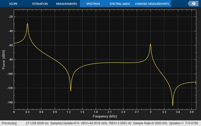
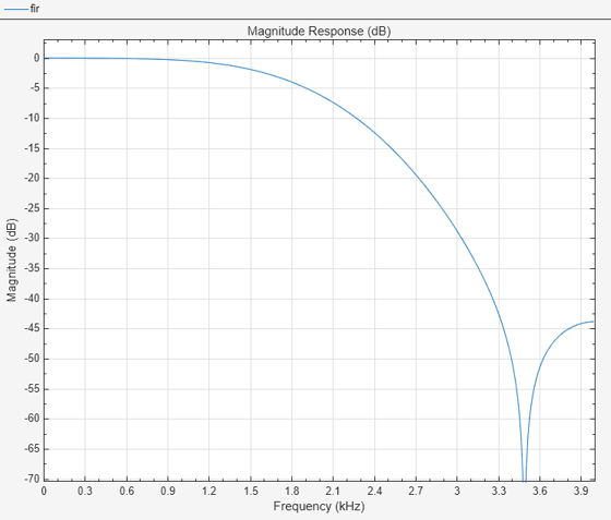
filteredResult = sink.Buffer; filterAnalyzer(fir,SampleRates=8000)
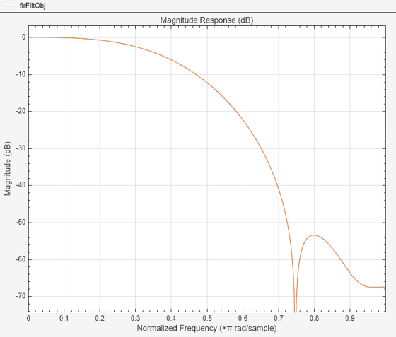
Design an FIR filter as a System object.
N = 10;
Fc = 0.4;
firFiltObj = designLowpassFIR(FilterOrder=N,CutoffFrequency=Fc,SystemObject=true)
firFiltObj = dsp.FIRFilter with properties:
        Structure: 'Direct form'
  NumeratorSource: 'Property'
        Numerator: [-1.2414e-18 -0.0126 -0.0247 0.0635 0.2748 0.3981 0.2748 0.0635 -0.0247 -0.0126 -1.2414e-18]
InitialConditions: 0
Show all properties
filterAnalyzer(firFiltObj)
Create a dsp.FIRFilter object, and set the NumeratorSource property to "Input port" so that you can vary the coefficients of the FIR filter through the input port during simulation.
firFilt = dsp.FIRFilter(NumeratorSource="Input port")
firFilt = dsp.FIRFilter with properties:
        Structure: 'Direct form'
  NumeratorSource: 'Input port'
InitialConditions: 0
Show all properties
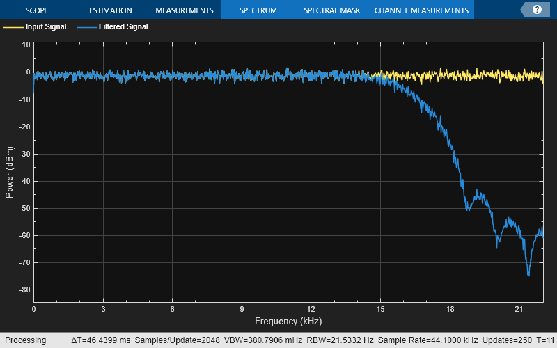
Create a spectrumAnalyzer object to visualize the spectra of the input and output signals.
spectrumScope = spectrumAnalyzer(SampleRate=44100,PlotAsTwoSidedSpectrum=false,... ChannelNames=["Input Signal","Filtered Signal"]);
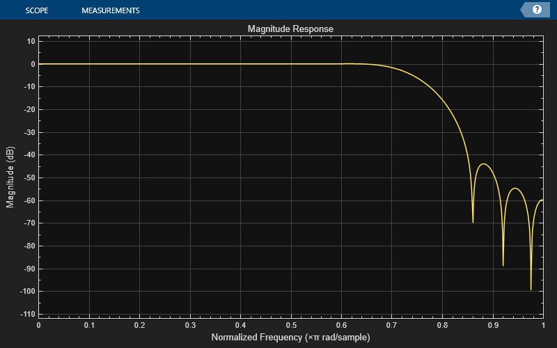
Create a dsp.DynamicFilterVisualizer object to visualize the magnitude response of the varying filter.
filterViz = dsp.DynamicFilterVisualizer(NormalizedFrequency=true);
Stream in random data and filter the signal using the dsp.FIRFilter object. Use the designLowpassFIR function to design the filter coefficients. By default, this function returns a vector of FIR filter coefficients. Assign these coefficients to the dsp.FIRFilter object.
Vary the cutoff frequency of the filter during simulation. The designLowpassFIR function redesigns the coefficients based on the updated filter specifications. Pass these updated coefficients to the FIR filter. Visualize the spectra of the input and filtered signals using the spectrum analyzer.
Fcut = 0.5; for idx = 1:500 num = designLowpassFIR(FilterOrder=30,CutoffFrequency=Fcut,Window="hann"); x = randn(1024,1); y = firFilt(x,num); spectrumScope(x,y); filterViz(num,1); Fcut = Fcut + 0.0005; end
Design and implement a lowpass FIR filter object using the designLowpassFIR function. The function returns a dsp.FIRFilter object when you set the SystemObject argument to true. To design the filter in single-precision, use the Datatype or like argument. Alternatively, you can specify any of the numerical arguments in single-precision.
firFilt = designLowpassFIR(FilterOrder=30,CutoffFrequency=0.5,Window="hann",... Datatype="single",SystemObject=true)
firFilt = dsp.FIRFilter with properties:
        Structure: 'Direct form'
  NumeratorSource: 'Property'
        Numerator: [0 2.1297e-19 0.0011 -1.8613e-18 -0.0048 4.8729e-18 0.0122 -8.7270e-18 -0.0251 1.2757e-17 0.0477 -1.6267e-17 -0.0960 1.8649e-17 0.3148 0.5000 0.3148 1.8649e-17 -0.0960 -1.6267e-17 0.0477 1.2757e-17 -0.0251 … ] (1×31 single)
InitialConditions: 0
Show all properties
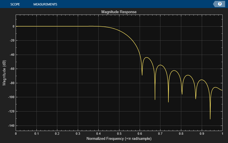
Create a dsp.DynamicFilterVisualizer object to visualize the magnitude response of the filter.
filterViz = dsp.DynamicFilterVisualizer(NormalizedFrequency=true); filterViz(firFilt)
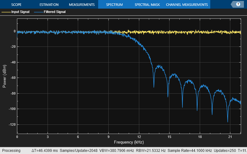
Create a spectrumAnalyzer object to visualize the spectra of the input and output signals.
spectrumScope = spectrumAnalyzer(SampleRate=44100,PlotAsTwoSidedSpectrum=false,... ChannelNames=["Input Signal","Filtered Signal"]);
Stream in random data and filter the signal using the dsp.FIRFilter object. Visualize the spectra of the input and filtered signals using the spectrum analyzer.
for idx = 1:500 x = randn(1024,1); y = firFilt(x); spectrumScope(x,y); end
Design an equiripple FIR halfband filter with the order of 24 and a transition width of 0.1 using the designHalfbandFIR function. Assign the filter coefficients to a dsp.FIRFilter System object.
b = designHalfbandFIR(FilterOrder=24,DesignMethod="equiripple"); hbFIR = dsp.FIRFilter(b);
Create a dsp.DynamicFilterVisualizer object and visualize the magnitude response of the filter.
dfv = dsp.DynamicFilterVisualizer(NormalizedFrequency=true); dfv(hbFIR);

Create a spectrumAnalyzer object to visualize the spectra of the input and output signals.
scope = spectrumAnalyzer(SampleRate=2, PlotAsTwoSidedSpectrum=false,... ChannelNames=["Input Signal","Filtered Signal"]);
Stream in random data and filter the signal using the FIR halfband filter.
for i = 1:1000 x = randn(1024, 1); y = hbFIR(x); scope(x,y); end

Since R2023b
Design a lowpass FIR filter using the designfilt function.
The filter is a minimum order filter with a passband frequency of 0.45 and a stopband frequency of 0.55 in normalized frequency units. The passband ripple is 1 dB and the stopband attenuation is 60 dB. Use the Kaiser window design method and set the SystemObject argument to true.
With these specifications, the designfilt function generates a dsp.FIRFilter System object™.
lpFIRFilter = designfilt("lowpassfir", ... PassbandFrequency=0.45,StopbandFrequency=0.55, ... PassbandRipple=1,StopbandAttenuation=60, ... DesignMethod="kaiserwin",SystemObject=true)
lpFIRFilter = dsp.FIRFilter with properties:
        Structure: 'Direct form'
  NumeratorSource: 'Property'
        Numerator: [1.2573e-04 -1.9141e-04 -2.7282e-04 3.7207e-04 4.9141e-04 -6.3325e-04 -8.0016e-04 9.9490e-04 0.0012 -0.0015 -0.0018 0.0021 0.0025 -0.0029 -0.0034 0.0040 0.0046 -0.0053 -0.0060 0.0069 0.0079 -0.0090 -0.0102 0.0116 … ] (1×74 double)
InitialConditions: 0
Show all properties
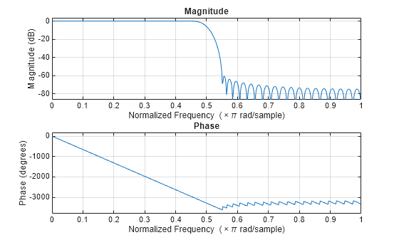
Visualize the magnitude and phase responses of this filter using freqz.
freqz(lpFIRFilter.Numerator)
Algorithms
This object implements the algorithm, inputs, and outputs described on the Discrete FIR Filter (Simulink) block reference page. The object properties correspond to the block parameters.
Extended Capabilities
Usage notes and limitations:
- Only the
Numeratorproperty is tunable for code generation. - See System Objects in MATLAB Code Generation (MATLAB Coder).
The dsp.FIRFilter System object supports SIMD code generation using Intel® AVX2 code replacement library under these conditions:
- Filter structure is set to
"Direct form"or"Direct form transposed". - Input signal is real-valued with real filter coefficients.
- When the filter structure is set to
"Direct form", the input signal can also be complex-valued with real or complex filter coefficients. - Input signal has a data type of
singleordouble.
The SIMD technology significantly improves the performance of the generated code. For more information, see SIMD Code Generation. To generate SIMD code from this object, see Use Intel AVX2 Code Replacement Library to Generate SIMD Code from MATLAB Algorithms.
For workflow and limitations, see HDL Code Generation for System Objects (HDL Coder).
Note
For a hardware-optimized FIR filter algorithm that supports HDL code generation, use the dsphdl.FIRFilter (DSP HDL Toolbox) System object. This object has hardware-friendly valid and reset control signals, and models exact hardware latency behavior. The object supports HDL code generation with HDL Coder™ tools.
Version History
Introduced in R2012a
Starting in R2025a, the Filter Design HDL Coder™ product is discontinued. So, this object no longer supports HDL code generation by using the generatehdl function. The object still supports code generation using HDL Coder tools.
The designfilt function generates a dsp.FIRFilter object when you specify"lowpassfir" and"highpassfir" filter responses and set theSystemObject flag totrue.
lpFIRFilter = designfilt("lowpassfir", ... PassbandFrequency=0.45,StopbandFrequency=0.55, ... PassbandRipple=1,StopbandAttenuation=60, ... DesignMethod="kaiserwin",SystemObject=true)
lpFIRFilter = dsp.FIRFilter with properties:
        Structure: "Direct form"
  NumeratorSource: "Property"
        Numerator: [1.2573e-04 -1.9141e-04 -2.7282e-04 3.7207e-04 … ] (1×74 double)
InitialConditions: 0
The Design Filter Live Editor task generates a dsp.FIRFilter object for lowpass FIR and highpass FIR filter responses when you select the Use a System object to implement filter check box in the task UI and run thedesignfilt code the task generates.