laser diode testing (original) (raw)
Author: the photonics expert
Definition: various test procedures applied to laser diodes in qualification, regular batch testing or burn-in
More specific terms: L–I–V characterization, burn-in testing, batch testing, spectral analysis
Categories:  photonic devices,
  light detection and characterization,
  laser devices and laser physics,
  optical metrology,
  methods
DOI: 10.61835/8ab [Cite the article](encyclopedia%5Fcite.html?article=laser diode testing&doi=10.61835/8ab): BibTex plain textHTML Link to this page 
Laser diodes can generally be expected to reach long lifetimes, often many tens of thousands of operation hours. Nevertheless, or actually just in order to reach such high reliability, they need to be tested under various circumstances:
- When the fabrication process is developed and qualified, particularly many tests are required, in that case addressing a wide range of performance aspects, such as threshold pump power, maximum output power, emission wavelength and bandwidth, spatial properties of the emission (e.g. the beam divergence angle in two directions or complete laser beam characterization) and possibly properties in pulsed operation, such as the temporal pulse shape.
- When the fabrication process is modified later on, e.g. concerning the laser diode design or some process parameters, or if new fabrication machines are introduced, similar tests may have to be performed once again to sure that everything works properly.
- When an established fabrication process is in operation, one regularly picks some samples for intensive screening in order to ensure a consistent product quality.
- Many laser diodes undergo a production burn in over e.g. several dozens of hours, which is applied to all fabricated diodes of a model, mainly in order to identify and remove those which would not reach the required performance or the specified lifetime, e.g. due to microscopic defects. Another aspect of burn in is that one then obtains a weaker change of performance parameters during later use. Testing may occur during the burn-in procedure (in situ test) or directly after it.
- One may want to test specific laser diodes when problems in an application are discovered. However, the diodes may then be at a location far from the manufacturing site, and comprehensive test equipment may not be available there.
For such tests, various kinds of testing procedures have been established, and there are specific testing systems which allow one to apply those in a consistent, reliable and hopefully cost-effective way. Such testing systems are mainly used on laser diode manufacturing sites, much less by laser users.
The expenses for building testing facilities and establishing precise testing procedures are substantial, even if that is done with experienced personnel. However, such activities are essential for achieving consistent performance with high reliability and lifetime. Note that a lack of reliability can have severe consequences in some application areas; for example, consider the failure of pump laser diodes of fiber amplifiers in undersea communication links. The benefits during fabrication can also be substantial, for example avoiding the fabrication of many faulty lasers before that can be detected.
For laser diodes produced in large quantities, the expenses per device may be fairly small, although the initial investment is substantial.
Common Challenges and Limitations of Laser Diode Testing
The ideal laser diode testing system would assess all possibly relevant characteristics with high accuracy and perfect reliability within a short time, and this with high convenience and at a low cost, also concerning energy consumption. Unfortunately, this is not realistic for various reasons:
Complexity
A quite complex and expensive testing facility would be required to provide a complete characterization. Therefore, one often limits the tested aspects to those which are considered to be essential and where there is a significant probability to find specifications violated.
For example, one may not test laser diodes concerning their spatial emission profile, assuming that it will be okay at least in those cases where the central specifications are fulfilled. However, one may then e.g. overlook the failure of a single emitter in a diode bar, which is associated with a certain distortion of the beam profile in the slow axis direction. It should be considered based on the requirements for the intended applications and the experience with past failures how far the testing should go.
Testing Time
While some tests can be performed very quickly – in a fraction of a second –, particularly lifetime and reliability tests (see below) can take long times. To a substantial extent, this can be mitigated with accelerated lifetime tests, but with certain limitations as explained below.
Even testing other aspects such as output power over wavelength tunability can take substantial time, for example if it is necessary to vary the device temperature in some range. Note that certain problems may occur only under specific circumstances, i.e., for some combination of parameters; that is particularly the case for tunable lasers.
Not only the testing itself costs time, but possibly also the transfer of tested laser diodes into the testing system, including proper mounting, electrical connections, temperature control etc. Such time may be minimized by tightly integrating testing into production lines, which however is tentatively more expensive than using standard testing systems.
Testing Conditions
Testing is usually done under carefully controlled conditions in order to avoid variable external influences which would make it difficult to interpret the results. However, it must be kept in mind that real-life operation of laser diodes may deviate in some respects, and particularly concerning lifetime and reliability that can have substantial influences. In reality, one may experience substantially more frequent failures e.g. due to current spikes (from pure quality laser diode drivers) or due to electrostatic discharges when connecting diodes. On the other hand, lifetimes can be substantially longer than specified when diodes are operated with a down-rated output power or at lower temperature.
Common Methods of Laser Diode Testing
Lifetime and Reliability Tests – Use of Accelerated Aging
Lifetime and reliability of lasers are some of the key properties for applications, and therefore need to be carefully optimized and tested, e.g. in the context of quality control. Different ways of failure may occur:
- Some lasers exhibit a steadily decreasing efficiency and output power, until the output power is insufficient for the application. Although the decrease of power may be suppressed by operation in constant power mode (with a closed feedback loop, e.g. based on internal photodiode and regulation of the drive current), eventually the device will reach the point where the needed output power is no longer achieved with an acceptable level of drive current. Various physical mechanisms can lead to such behavior – for example, the growth of dislocations in the semiconductor lattice, the degradation of the output facet by oxidation, the degradation of electrode structures due to metal diffusion, the degradation of electrical bonds and the degradation of heat sinks.
- In other cases, one observes instant complete failure, which often involves some kind of run-away effect. For example, there can be catastrophic optical damage (COD) of the output facet, where an initial small defect leads to increased light absorption, which in turn increases the damage and the absorption, so that complete damage occurs within a short time. That risk exists particularly for edge-emitting lasers optimized for high brightness and operated near or above the rated maximum current, and/or at elevated temperatures.
Some failure mechanisms are systematic and occur with similar rates for all fabricated lasers of a certain model. The probability of final failure then increases with increasing operation time, with a substantial impact of operation parameters such as drive current and temperature. Sudden complete damage may occur as a consequence of steady degradation (e.g. gradual oxidation of the facet, eventually getting into a destructive run-away effect) after a relatively long operation times. In other cases, it occurs early on (as “infant mortality”) as a result of microscopic defects which were created during fabrication or were even present in the used semiconductor wafer. One will typically find that some small fraction of the fabricated lasers will die early on due to such effects, while most of the others live much longer.
Plotting the probability of failure versus operation time, one often obtains the typical “bathtub curve”: frequent failures in the first hundred hours, much higher reliability (with a low rate of random faults) during many hours thereafter, and finally an increasing probability of failure due to wear out when the usual end of life is reached. A quantitative life expectancy, e.g. in terms of mean time between failures (MTBF), may also be calculated from such parameters based on certain models.
Life tests and reliability tests are naturally time-consuming. Obviously, it is not practical to test a badge of laser diodes for many thousand hours before confirming that specifications are met and a fabrication process can continue. Even the aspect of occupying an expensive testing facility for such long times would not be acceptable. Therefore, methods of accelerated aging are widely applied – typically implemented such that laser diodes are intentionally operated at substantially increased temperatures, where certain aging processes are known to progress much faster than normal. In many cases, the rate of aging is known to follow an exponential law, i.e., to be proportional to <$\exp(E_\textrm{a} / k_\textrm{B} T)$>, where <$E_\textrm{a}$> is called an activation energy, <$k_\textrm{B}$> is Boltzmann's constant, and <$T$> is the operation temperature. One then typically adjusts the device temperature and the testing conditions such that the aging occurs at a rate which is several orders of magnitude faster than normal, so that the degradation of performance (e.g. of the optical output power) and total failure of diodes is seen accordingly sooner.
Accelerated aging can also be used during burn in: it allows one to identify defect lasers in a shorter time, so that these can be removed and the delivered lasers exhibit a correspondingly higher reliability.
Unfortunately, accelerated aging is not perfectly simple and reliable in all respects:
- In practice, one first needs to establish the exponential law and the corresponding activation energy. That requires a significant number of tests, some of which have to be done over a rather long time. After all, the activation energy is usually not known a priori.
- There may be additional degradation processes exhibiting a different behavior, which can thus not be accurately assessed with accelerated aging tests. For example, catastrophic optical damage of the facets critically depends on the optical intensity, which may be relatively low during high-temperature tests due to the reduced laser efficiency.
- Another problem is that operation at elevated temperatures does not only change the emission wavelength, but usually also reduces the power conversion efficiency or (for strong temperature increases) even does not allow lasing at all. One may still do the testing with electric current flowing through the laser diodes but no lasing; the question is then whether the missing optical intensity has any profound impact on the aging and reliability. It may well have such an impact, as it is known that catastrophic optical damage at the laser output facet is a common failure mode. In some cases, one regularly brings the tested diodes to a lower temperature to do regular L–I–V testing (see below) during short time intervals, but that does of course not just aging based on optical intensity.
In conclusion, while the method of accelerated aging can save very much time, it still requires substantial time for establishing the test, and various uncertainties remain.
Note also that practically achieved lifetime and reliability can depend on various external conditions, such as the operation temperature (which itself can be affected by details of the cooling, e.g. by the chemical composition of cooling water which can lead to degradation of cooling water channels), the occurrence of optical feedback, and on voltage spikes, caused by the handling or by disturbances in the electric network. Since such conditions can be substantially different between testing sites and the situation in the real application, one will usually minimize any disturbing effect during testing, but should keep in mind that real-life reliability and lifetime may be substantially worse if the conditions are not perfect.
Another potential problem are spoiled tests due to power outages (blackouts), particularly in countries with a poor electrical infrastructure. Tests for low-power diodes may be relatively easily protected with an uninterruptible power supply based on rechargeable batteries, but it must be ensured that the testing device can handle possibly still occurring discontinuities of the supply voltage. (It is preferable to have the battery pack and power stabilization integrated into the device, with the manufacturer taking responsibility for the system as a whole.) For testing high-power diodes, particularly when many of them are tested in parallel, an uninterruptible power supply with a capacity for several hours of battery-powered operation may become too expensive. One should then at least be able to secure the measurement data and continue the test when the power comes back. Otherwise, substantial time and also tested lasers may be lost.
L–I–V Characterization
L–I–V (or LIV) characterization means that the optical output power and the voltage across the diode contacts are measured as functions of the junction current. The abbreviation L–I–V for light–current–voltage is common, but actually quite awkward: with L one means the power <$P$> of the emitted light, and the official formula symbol for the voltage is actually <$U$> rather than <$V$>. Therefore, P–I–U testing (or perhaps P–C–V for power–current–voltage) would actually be more appropriate, but is not common.
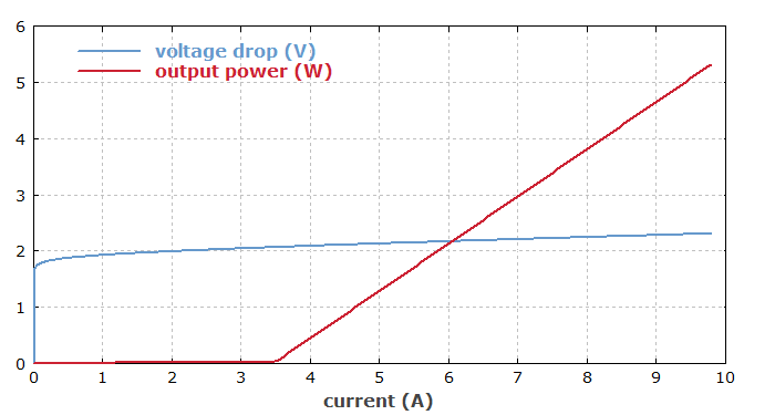
Figure 1: L–I–V curves for a high-power laser diode. While the optical power become substantial only above the threshold current, the voltage drop grows steadily with increasing current.
For L–I–V measurements, one uses a constant current source (enforcing a certain electric current irrespective of the encountered electrical resistance), connected to the laser diode pins, a voltmeter connected in parallel, and an optical power meter. The latter might be realized with an integrating sphere and a photodiode, where the former leads to insensitivity of the measured power against the spatial emission characteristics (which might well depend on the drive current). (Such aspects of course do not apply to fiber-coupled diode lasers.) The used photodetector should ideally exhibit a weak wavelength dependence, since the emission wavelength can vary in a certain range.
The following key properties of a laser diode can be obtained:
- There is a certain threshold current, below which there is no laser operation. The optical output power is not exactly zero below threshold, but quite low. The exact value of the threshold may be determined as the value where a certain low power level is reached, or better by linear downward-extrapolation of values for higher currents. Good repeatability of results is important.
- The maximum output power is usually obtained for the maximum drive current, although in some situations this is not the case.
- The slope efficiency (in units of W/A) can be calculated as the maximum output power divided by the difference between maximum current and threshold current, although this makes sense only if the curve is close to linear.
- The measured voltage drop can also be of interest, e.g. for detecting certain anomalies. For reliable results, a well-defined electrical contact is required. Ideally, one uses a four-wire system with two wires for applying the test current and another two wires for measuring the voltage.
Generally, a high precision of the measurement results (and temperature stabilization) is desirable, so that it is clear that slightly falling or rising values are due to changes in the tested diodes rather than drifts of the measurement system.
Automated L–I–V characterization systems can have various convenient features:
- They can rapidly ramp the drive current from zero to an appropriate maximum value, sometimes providing all the data within well below a second. (Note that the steady-state output power of a laser diode is reached very quickly.) That is particularly useful for testing of lasers which are not yet equipped with cooling features. One may also apply multiple rectangular current pulses with small rise and fall time at different levels with a low duty cycle. (The low duty cycle also has the benefit that due to an internal capacitor for energy storage, the testing device does not need a powerful power supply.) Note that a high precision must be insured, and this can set limits for the achievable measurement time.
- Versatile devices can do such tests in a wide range of currents and optical powers, but usually not the full range from lowest-power diodes to high-power diode bars or even diode stacks. One may expect, however, that a single system is at least suitable for diode bars in a wide range of powers, while another system may be suitable for many low-power lasers.
- It can be convenient to have a range of mounting options for laser tests at different stages in the production chain: for laser chips and for packaged lasers.
- The results may be displayed in graphical form on a screen (either in the testing device or at a connected computer), together with some key parameters such as threshold current, maximum output power and slope efficiency.
- The measurement data may not only be directly displayed for informing an operator, but may also be transferred to a computer (e.g. via USB interface); the data can then be stored, also keeping the association with specific devices, and output in other forms, e.g. as data sheets printed on small labels which can be attached to devices. For unusual results, an automatic warning may be signaled. The connected computer may also be used for setting all the test parameters (avoiding error-prone manual settings).
- The measurements can be carried out under very controlled conditions, including the device temperature. For example, one may perform the measurement so quickly that the internal device temperature does not substantially deviate from room temperature, which itself is stabilized. Alternatively, the diodes may be mounted on a temperature-controlled metal heat sink, and the system may take measurements at different temperatures.
- It can be valuable also to measure the emission wavelength or even the full emission spectrum as a function of the current and/or temperature.
- For rapid characterization of multiple lasers, some systems are able to characterize a large number of laser diodes simultaneously. Note that for statistically significant results, one always needs to test a sufficiently high number of devices. Suitable statistical algorithms can be implemented in corresponding software, either in the testing system or outside under the responsibility of the user.
Although the basic principle of L–I–V testing is simple, overall the matter can be complex, considering the many desirable details and the required precision. Therefore, using dedicated high quality laser testing instruments is often a good solution, despite the substantial cost. Still, substantial experience is required at least for reliable testing in manufacturing environments.
L–I–V tests may not only be applied to fully packaged lasers, but also at earlier steps in the fabrication in order to recognize potential problems early on and to avoid unnecessary further processing of defect laser chips (which contributes much to the fabrication cost). For example, edge-emitting lasers may undergo a first testing directly after slicing the semiconductor wafer and coating the end faces. Easier testing is possible for surface-emitting semiconductor lasers like VCSELs.
Optical Spectrum
The optical spectrum of the laser emission is relevant for many applications. For example, diode-pumped lasers based on typical laser crystals like Nd:YAG have relatively narrow-band pump absorption features. Therefore, drifts of the center wavelength and/or a widened spectrum can seriously compromise the pump absorption efficiency and thus the laser performance.
It can thus be important to characterize the optical spectrum, using some kind of optical spectrum analyzer. For multimode lasers, it should be kept in mind that the emission spectrum is not necessarily identical for all parts of the laser, e.g. for the different emitters of a diode bar. Usually, one will try to collect the information for spectral analysis such that most of the emitted light is collected, despite the necessity to provide sufficient optical attenuation for the spectrometer.
In the case of wavelength-tunable lasers, one will usually want to record the spectrum for different settings of the output wavelength, e.g. in order to verify the whole tuning range and smooth tuning throughout that range. The impact of temperature changes may also be relevant, unless the device is specified for operation at constant temperature. Particularly for single-frequency lasers, multi-hop-free tuning may have to be checked. Specialized characterization setups are needed for such tasks.
Spatial Emission Profiles
In some cases, the spatial emission profile of laser diodes is of high interest, e.g. for tracking down problems with single failed emitters of diode bars, or when highly uniform illumination is required. Both the near-field and far-field properties can be of interest:
- Without any optical elements e.g. for beam collimation, the output of a laser diode is usually strongly divergent, and the resulting intensity profile in a moderate distance is essentially determined by the far-field pattern, i.e., by the angular distribution of the radiation. Here, the failure of a single emitter of a diode bar, for example, will generally not have a very pronounced effect because the ordinary emission coil of that emitter would strongly overlap with that of other emitters. That implies that defect emitters could not be reliably identified that way.
- If the radiation is collimated and focused again, the near-field pattern at the laser diode output will usually reappear at the beam focus, including features such as those from a defect emitter. (Although the defect is not visible in the collimated beam, it is not “forgotten” during the passage through the optical system.) As laser applications often involve focusing of the radiation, such defects can be quite relevant.
It is thus clear that a comprehensive characterization of spatial beam profiles should address both the near and far field, using suitable optical elements. Still, a full spatial characterization will usually not be achieved, particularly for multi-emitter lasers, where complicated phenomena such as partial coherence between different emitters (particularly under conditions of optical feedback) can arise, and where the emission pattern can change substantially with changes of drive current or other conditions. A much simpler situation is encountered for essentially diffraction-limited low-power single emitters, where unusual emission patterns can basically occur only in the case of facet damage.
Pulse Features
While many laser diodes are used in continuous-wave operation or in quasi-continuous-wave operation, there are also pulsed laser diodes, e.g. based on the technique of gain switching for generating picosecond pulses (→ picosecond diode lasers). One may then need to measure the temple profile, i.e., the output power as a function of time during a pulse. For that, one will usually use a very fast photodiode, possibly with an optical attenuator.
For longer pulses with correspondingly higher energies, it may happen that the rise of junction temperature during the pulse leads to a frequency chirp, i.e., to a time-dependent emission spectrum. A spectrometer may often not be suitable for monitoring such details.
More to Learn
Encyclopedia articles:
Suppliers
Questions and Comments from Users
Here you can submit questions and comments. As far as they get accepted by the author, they will appear above this paragraph together with the author’s answer. The author will decide on acceptance based on certain criteria. Essentially, the issue must be of sufficiently broad interest.
Please do not enter personal data here. (See also our privacy declaration.) If you wish to receive personal feedback or consultancy from the author, please contact him, e.g. via e-mail.
By submitting the information, you give your consent to the potential publication of your inputs on our website according to our rules. (If you later retract your consent, we will delete those inputs.) As your inputs are first reviewed by the author, they may be published with some delay.