Finite-difference solution of scattering by a rectangular cylinder (TM) using exact mesh termination (original) (raw)
Abstract
Finite Difference Techniques for solution of "steady state'' frequency domain Helmboltz equation is quite simple and straightforward. Howeuer, for open regions, the finite difference mesh needs to be terminated so that the proper boundary conditions are imposed for the sohtion. A hybrid method is described in this paper which guarantees that the boundaly conditions generated for the termination of the open region mesh is exact. The conditions are generated from the Green's functions. The technique is applied to the solution of electromagnetic scattering by conducting cylinders (TM case).
Figures (4)
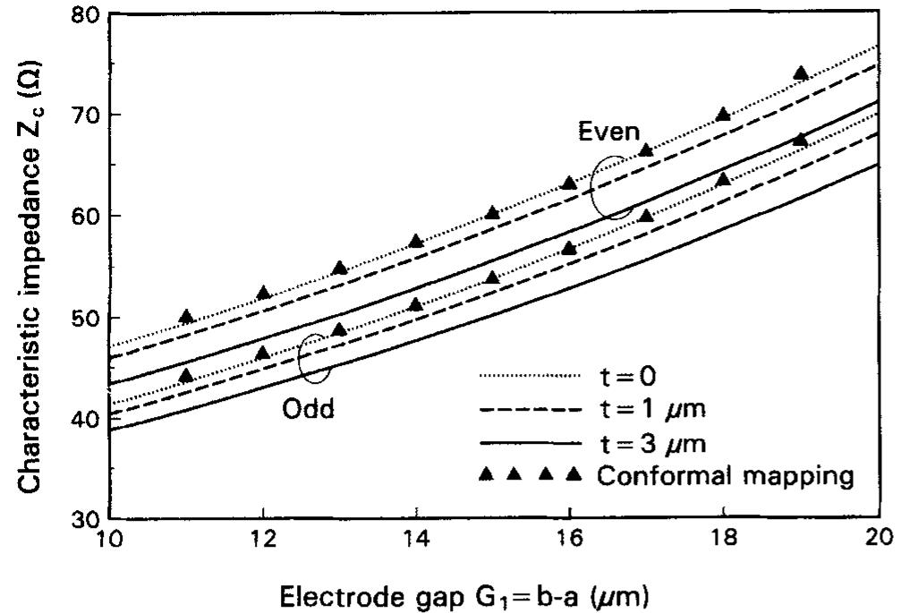
Figure 5 Calculated characteristic impedances as a function of electrode gap G, = b — a. The parameter is the electrode thickness ¢
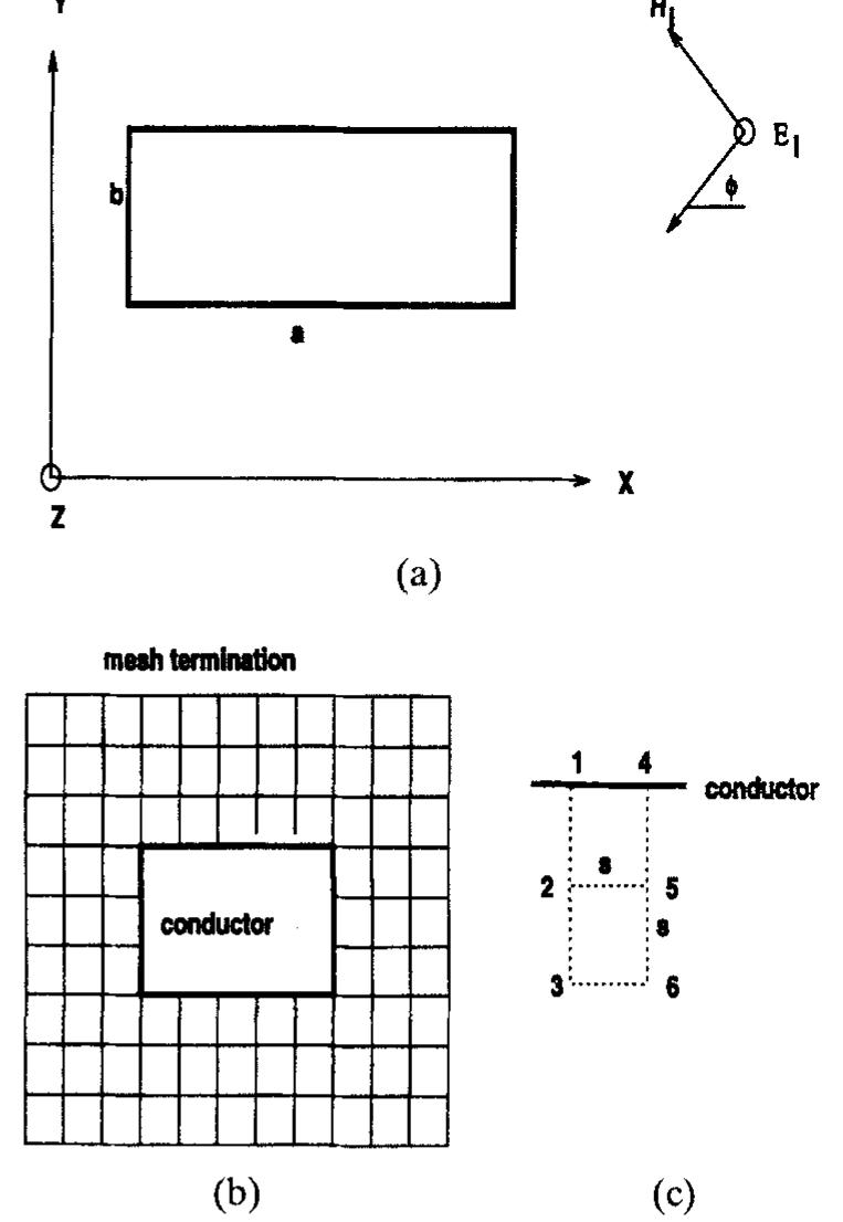
Figure 1 (a) Cross section of a rectangular cylindrical conductor, acting as a scatterer; (b) square mesh for the system of (a); (c) points used to evaluate magnetic field
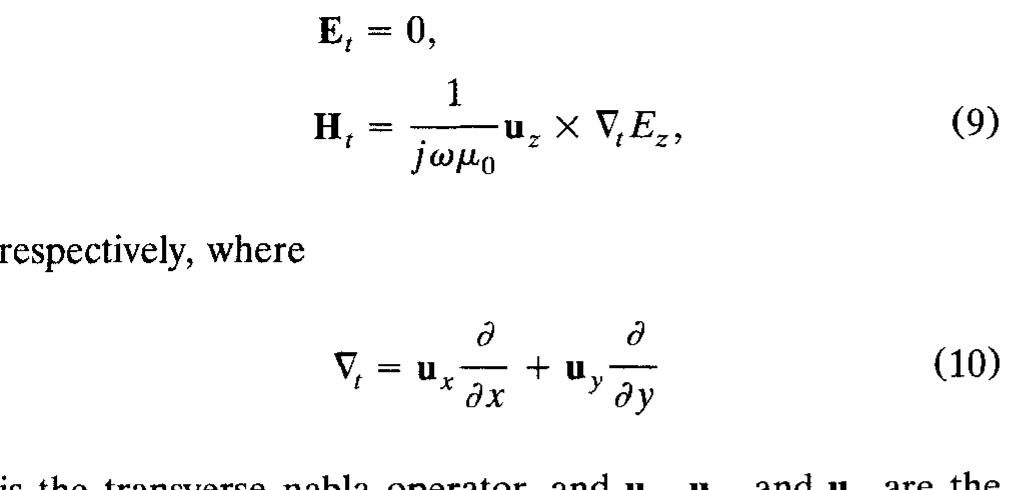
The transverse components of the electric and magnetic ields are
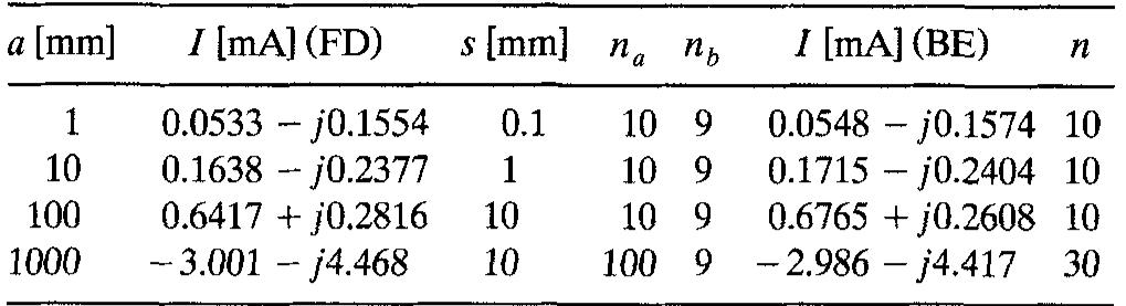
TABLE 1 Total current (/) on the cylinder of Figure 1, for a=b, 6 =0, E,;=1V/m, and f = 1 GHz, obtained by the finite-difference method (FD) and the boundary-element method (BE). Given also are the step size (s), the number of steps along a(n,), and the number of pulses per conductor side (n) for the boundary-element method. The phase of the electric field is zero at the conductor axis

Loading Preview
Sorry, preview is currently unavailable. You can download the paper by clicking the button above.
References (24)
- F. Mernyei, I. Aoki, and H. Matsuura, "New Filter Element for MMICs: Triple Coupled CPW Lines," Electron. Lett., Vol. 30,
- G. G. Gentili and G. Macchiarella, "Quasi-Static Analysis of Shielded Planar Transmission Lines with Finite Metallization Thickness by a Mixed Spectral-Space Domain Method," IEEE Trans. Microwaue Theory Tech., Vol. M1T-42, 1994, pp. 249-255.
- H. Jin, R. Vahldieck, M. Bklanger, and Z. Jacubczyk, "A Mode Projecting Method for the Quasi-Static Analysis of Electrooptic Device Electrodes Considering Finite Metallization Thickness and Anisotropic Substrate," IEEE J. Quantum Electron., Vol.
- H. Jin, M. BBlanger, and Z. Jacubcqk, "General Analysis of Electrodes in Integrated-Optics Electrooptic Devices," IEEE J. Quantum Electron., Vol. QE-27, 1991, pp. 243-251.
- W. Heinrich, "Quasi-TEM Description of MMIC Coplanar Lines Including Conductor-Loss Effects," IEEE Trans. Microwave Theory Tech., Vol. MTT-41, 1993, pp. 45-52. 1994, pp. 2150-2151.
- QE-27, 1991, pp. 2306-2314.
- H. E. Green, "The Numerical Solution of Some Important Transmission Line Problems," IEEE Trans. Microwave Theory Tech., Vol. M7T-13, 1965, p. 676.
- Z. Pantic and R. Mittra, "Quasi-TEM Analysis of Microwave Transmission Lines by the Finite-Element Method," IEEE Trans. Microwave Theory Tech., Vol. M7T-34, 1986, pp. 1096-1103.
- A. Khebir, A. Kouki, and R. Mittra, "High-Order Asymptotic Boundary Condition for the Finite Element Modeling of Two- Dimensional Transmission Line Structures," IEEE Trans. Microwaue Theory Tech., Vol. MTT-38, 1990, pp. 1433-1437.
- K. Kawano, K. Noguchi, T. Kitoh, and H. Miyazawa, "A Finite Element Method (FEM) Analysis of a Shielded Velocity-Matched TkLiNbO, Optical Modulator," IEEE Photon. Technol. Lett.,
- T. Honma, and I. Fukai, "An Analysis for the Equivalence of Boxed and Shielded Strip Lines by a Boundary Element Method," Trans. IECE Jpn., Vol. J65-B, 1982, pp. 497-498.
- T. Chang, and C. Tan, "Analysis of a Shielded Microstrip Line with Finite Metallization Thickness by the Boundary Element Method," IEEE Trans. Microwave Theory Tech., Vol. M7T-38,
- S. A. Ivanov and G. L. Djankov, "Determination of the Charac- teristic Impedance by a Step Current Density Approximation," IEEE Trans. Microwave Theory Tech., Vol. M1T-32, 1984, pp.
- D. Marcuse, "Electrostatic Field of Coplanar Lines Computed with the Point Matching Method," IEEE J. Quantum Electron.,
- C. Nguyen, "Broadside-Coupled Coplanar Waveguides and Their End-Coupled Band-Pass Filter Applications," IEEE Trans. Mi- crowave Theory Tech., Vol. MTT-40, 1992, pp. 2181-2189.
- N. H. Zhu, Z. Q. Wang, and W. Lin, "On the Accuracy of Analytical Expressions for Calculating the Parameters of Copla- nar Strips on a Finitely Thick Substrate," Microwaue Opt. Tech- nol. Lett., Vol. 8, 1995, pp. 160-164.
- E. Drake, F. Medina, and M. Horno, "Quasi-TEM Analysis of Thick Multistrip Lines Using an Efficient Iterative Method," Microwave Opt. Technol. Lett., Vol. 5, 1992, pp. 530-534.
- K. Kawano, K. Noguchi, T. Kitoh, and H. Miyazawa, "A Finite Element Method (FEM) Analysis of a Shielded Velocity-Matched Ti:LiNbO, Optical Modulator," IEEE Photon. Technol. Lett.,
- D. H. Naghski, J. T. Boyd, H. E. Jackson, S. Sriram, S. A. Kingsley, and J. Latess, "An Integrated Photonic Mach-Zehnder Interferometer with No Electrodes for Sensing Electric Fields,'' J. Lightwave Technol., Vol. 12, 1994, pp. 1092-1098. REFERENCES
- A. R. Djordjevic, T. K. Sarkar, T. Roy, and M. Salazar, "An Exact Method for Simulating Boundary Conditions for Mesh Termina- tion in Finite-Difference Techniques," Microwaue Opt. Technol. Lett., to be published.
- A. R. Djordjevic, T. K. Sarkar, S. M. Rao, "Analysis of Finite Conductivity Cylindrical Conductors Excited by Axially-fndepen- dent TM Electromagnetic Field," ZEEE Trans. Microwave Zheoiy Tech., Vol. M'IT-33, No. 10, Oct. 1985, pp. 960-966.
- R. F. Harrington, Field Computation by Moment Methods, MacMil- lan, New York, 1968.
- A. R. Djordjevic, R. F. Harrington, T. K. Sarkar, and M. B. Bazdar, Matrix Parameters for Multiconductor Transmission Lines, Artech House, Boston, 1989. Received 4-1 1-95; revised 6-6-95
- Microwave and Optical Technology Letters, 10/3, 186-189
FAQs
![]()
AI
What numerical methods are compared in this study of electromagnetic scattering?add
The research compares a finite-difference approach with a boundary-element method, demonstrating excellent agreement in computed total currents.
What experimental setup is used for analyzing scattering by the rectangular cylinder?add
The setup involves a square cross-section cylinder illuminated by a 1 GHz plane wave, with current measurements taken under various dimensions.
How does the proposed method handle boundary conditions for mesh termination?add
The method establishes exact boundary conditions for mesh termination based on evaluating electric fields at mesh nodes, enhancing computational accuracy with second-order differences.
What types of structures can the proposed method be applied to besides cylinders?add
The technique can also apply to asymmetric coplanar waveguides, multilayered dielectric substrates, and structures relevant to optical integrated circuits.
What issues arise with the finite-difference method under certain parameters?add
Parasitic resonances occur for certain dimensions (e.g., a=100 mm) when mesh parameters exceed specific limits, leading to divergent results.