T Flip Flop (original) (raw)
Last Updated : 14 Jan, 2026
Flip-flop is a term that comes under digital electronics, and it is an electronic component that is used to store one single bit of information. Since Flip Flop is a sequential circuit its input is based upon two parameters, one is the current input and the other is the output from the previous state.
- It has two outputs, both are complements of each other.
- It may be in one of two stable states, either 0 or 1.

Basic diagram of Flip Flop
**T flip flop is known as **Toggle Flip Flop because it is able to toggle its output depending upon on the input. Toggle basically indicates that the bit will be flipped i.e., either from 1 to 0 or from 0 to 1. Here, a clock pulse is supplied to operate this flip flop, hence it is a clocked flip-flop.
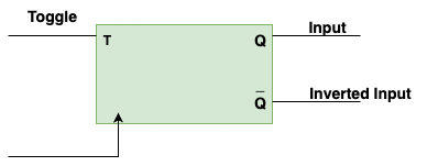
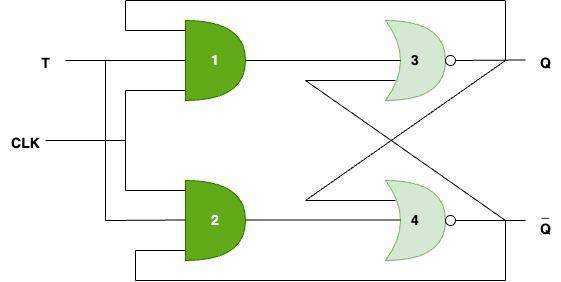
Block Diagram of T Flip Flop
Here block diagram contains Toggle and clock inputs, Q and Q' is the complemented inputs.
Truth Table of T Flip Flop
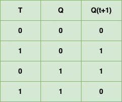
Truth Table of T Flip Flop
- Here, T is the Toggle input, Q is present state input, Qt+1 is the next state output.
- From here we can see that, whenever Toggle (T) is 0, next state output (Qt+1) is same as current state input (Q).
- Whenever Toggle (T) is 1, next state output (Qt+1) will be complement of current state input (Q) which means it gets toggled.
Characteristic Equation
- The characteristic equation tells us about what will be the next state of flip flop in terms of present state.
- In order to get the characteristic equation, K-Map is constructed which will be shown as below:
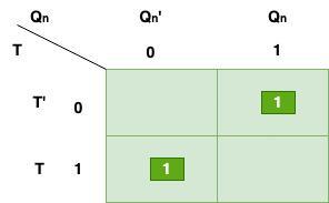
K-Map for T Flip Flop
- If we solve the above K-Map then the characteristic equation will be
**Q(n+1) = TQn’ + T’Qn = T ⊕ Qn
Excitation Table
Excitation Table basically tells about the excitation which is required by flip flop to go from current state to next state.
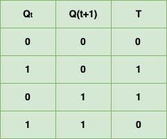
Excitation Table for T Flip Flop
- Here, whenever T is 0, Qt+1 is same as input Q.
- And, whenever T is 1, Qt+1 is compliment of input Q.
Working of T Flip Flop
**Case 1: Let's say, T = 0 and clock pulse is high i.e, 1, then output of both, AND gate 1, AND gate 2 will be 0, gate 3 output will be Q and similarly gate 4 output will be Q' so both the values of Q and Q' are same as their previous value, which means Hold state.
**Case 2: Let's say, T=1, then output of both AND gate 1 will be (T * clock * Q), and since T and clock both are 1, then the output of AND gate 1 will be Q, and similarly output of AND gate 2 will be (T * clock * Q') i.e, Q'. Now, gate 3 output will be (Q'+Q)' and let's say Q' is zero, then gate 3 output will be (0+Q)' which means Q' and similarly gate 4 output will be (Q+Q')' and since Q' is zero, so gate 4 output will be Q' which means 0 as Q' is zero. Hence in this case we can say that the output toggles, because T=1.
Construction of T Flip Flop
We can construct T flip flops in three ways namely:
- By using SR Flip Flops.: Uses S and R inputs to set or reset the current output state.
- By using D Flip Flops: By using D Flip Flops: The next output state is directly taken from the D input at the clock edge.
- By using JK Flip Flops: J and K inputs allow toggle, set, or reset of the flip-flop output.

Ways to Construct T Flip Flop
Applications of T Flip Flop
There are numerous applications of T Flip Flop in digital system, which are listed below:
- **Counters: T Flip Flops are used in counters. Counters counts the number of events that occurs in a digital system.
- **Data Storage: T Flip Flops used to create memory which are used to store data, when the power is turned off.
- **Synchronous logic circuits: T flip-flops can be used to implement synchronous logic circuits, which are circuits that perform operations on binary data based on a clock signal. By synchronizing the logic circuit's operations to the clock signal using T flip-flops, the circuit's behavior can be made predictable and reliable.
- **Frequency division: It is used to divide the frequency of a clock signal by 2. Flip-flop will toggle its output every time the clock signal transitions from high to low or low to high, hence dividing the clock frequency by 2.
- **Shift registers: T flip-flops can be used in shift registers which are used to shift binary data in one direction.