VHDL code for AND and OR Logic Gates (original) (raw)
Last Updated : 12 Jul, 2025
Prerequisite - Introduction of Logic Gates
Design and implement the AND and OR logic gates using VHDL (VHSIC Hardware Description Language) programming language.
Different Types of VHDL Modelling Styles
The architecture of VHDL code is written in three different coding styles :
- Dataflow Modelling
- Behavioral Modelling
- Structural Modelling
1. Logic Development for AND Gate: The AND logic gate can be realized as follows -
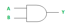
The truth table for AND Gate is:
| A | B | Y = A AND B |
|---|---|---|
| 0 | 0 | 0 |
| 0 | 1 | 0 |
| 1 | 0 | 0 |
| 1 | 1 | 1 |
Implementation of Dataflow Modelling - Below is the implementation of the above logic in the VHDL language (Dataflow Modelling).
-- VHDL Code for AND gate
-- Header file declaration
library IEEE; use IEEE.std_logic_1164.all;
-- Entity declaration
entity andGate is
**port**(A : in std_logic;      -- _AND gate input_
     B : in std_logic;      -- _AND gate input_
     Y : out std_logic);    -- _AND gate output_
end andGate;
-- Dataflow Modelling Style -- Architecture definition
architecture andLogic of andGate is
begin
Y <= A AND B;end andLogic;
2. Logic Development for OR Gate: The OR logic gate can be realized as follows -
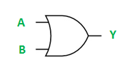
The truth table for OR Gate is:
| A | B | Y = A OR B |
|---|---|---|
| 0 | 0 | 0 |
| 0 | 1 | 1 |
| 1 | 0 | 1 |
| 1 | 1 | 1 |
Implementation of Dataflow Modelling - Below is the implementation of the above logic in the VHDL language (Dataflow Modelling).
-- VHDL Code for OR gate
-- Header file declaration
library IEEE; use IEEE.std_logic_1164.all;
-- Entity declaration
entity orGate is
**port**(A : in std_logic;      -- _OR gate input_
     B : in std_logic;      -- _OR gate input_
     Y : out std_logic);    -- _OR gate output_
end orGate;
-- Dataflow Modelling Style -- Architecture definition
architecture orLogic of orGate is
begin
Y <= A OR B;end orLogic;