Introduction of Logic Gates (original) (raw)
Last Updated : 28 Dec, 2024
In Boolean Algebra, there are three basic operations, +,\:.\:,\:^\prime which are analogous to disjunction, conjunction, and negation in propositional logic . Each of these operations has a corresponding logic gate. Apart from these, there are a few other logic gates as well. It was invented by George Boole.
Table of Content
What is a Logic Gate?
A gate can be defined as a digital circuit that can allow a signal (electric current) to pass or stop. A type of gate that allows a signal to pass through when certain logical conditions are met. Different logic gates have different logical conditions.
**Truth Table: A truth table is a table that shows all possible combinations of inputs and outputs for a logic gate.
Types of Gate
Given Below are the different types of Logic Gates :
- AND Gate(.)
- OR Gate(+)
- NOT Gate(')
- XOR Gate
- NAND Gate
- NOR Gate
- XNOR Gate
- Buffer Gate
- Universal Logic Gates
**AND Gate(.)
The AND gate gives an output of 1 when if both the two inputs are 1, it gives 0 otherwise. For n-input gate if all the inputs are 1 then 1 otherwise 0.The AND gate operation is similar to the standard multiplication of 1s and 0s.The (.) dot represents the AND operation.

AND Gate
**The Expression for AND gate can be given as
**X=(A.B)
Where,
X is the output of gate
A and B are the inputs of the gate
**OR Gate(+)
The OR gate gives an output of 1 if either of the two inputs are 1, it gives 0 otherwise. For n-input gate if all the inputs are 0 then 0 otherwise 1.The OR Operation is represented by the +.

OR Gate
The Expression for OR Gate is given as
**X=A+B
Where,
X is the output of gate
A and B are the inputs of the gate
**NOT Gate(')
The NOT gate gives an output of 1 if the input is 0 and vice-versa. It is also known as Inverters. In Boolean algebra NOT operation is represented by bar over the variable such as \overline{A}.

NOT Gate
The Expression for NOT Gate can be given as
Y=\overline{A}
Where,
X is the output of gate
A is the inputs of the gate
**XOR Gate
The XOR gate gives an output of 1 if either both inputs are different, it gives 0 if they are same. For n-input gate if the number of input 1 are odd then it gives 1 otherwise 0.For a two-input XOR gate it means that the output is true only if exactly one of the inputs is true.

XOR Gate
The Expression for XOR Gate can be given as
**X = A’B + AB’
Where,
X is the output
A and B are the inputs
Thus we need 5 NOR GATE to implement XOR GATE.
**NAND Gate
The NAND gate (negated AND) gives an output of 0 if both inputs are 1, it gives 1 otherwise. For n-input gate if all inputs are 1 then it gives 0 otherwise 1.The Term "NAND" can be said as "Not AND".

NAND Gate
The Expression for NAND Gate can be given as
Y=\overline{A.B}
Where,
Y is the Output of gate
A and B is the input of gate
**NOR Gate
The NOR gate (negated OR) gives an output of 1 only if both inputs are 0, it gives 0 otherwise. For n-input gate if all inputs are 0 then it gives 1 otherwise 0.The "NOR" can be said as "NOT OR".

NOR Gate
The Expression for NOR Gate can be given as
Y=\overline{A+B}
Where,
Y is the Output of gate
A and B is the input of gate
**XNOR Gate
The XNOR gate (negated XOR) gives an output of 1 if both inputs are same and 0 if they are different. For n-input gate if the number of input 1 are even then it gives 1 otherwise 0 or if the number of input 0 is even then the output is 1, otherwise 0'. The "XNOR" can be said as "Exclusive NOR".
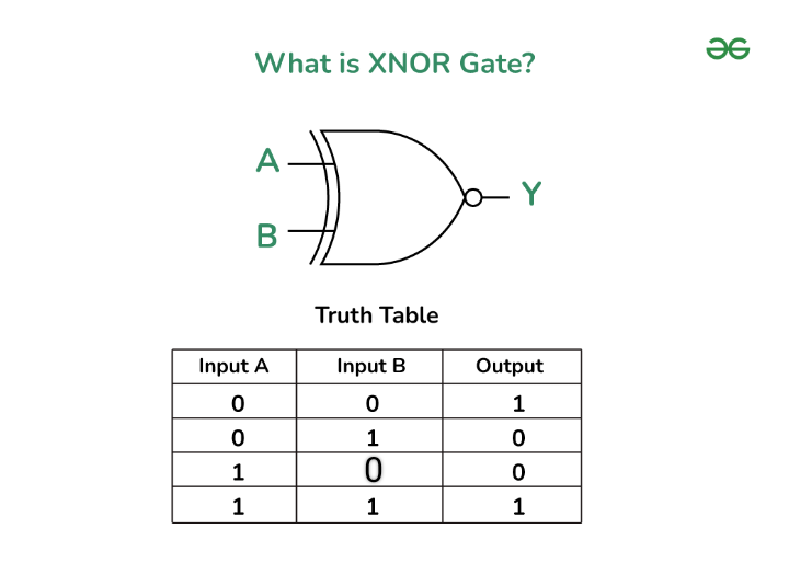
XNOR Gate
The Expression for XNOR Gate can be given as
__Y_=_A_⊙__B
Where,
Y is the Output of gate
A and B is the input of gate
**Buffer Gate
A Buffer Gate is a digital logic gate that amplifies a signal. It doesn't change the logic state (it outputs exactly what is input), but its primary purpose is to ensure that the signal can drive more circuits without weakening. Essentially, a buffer isolates the input from the output, making the output more robust.
- If the input is 1 , the buffer outputs 1 .
- If the input is 0 , the buffer outputs 0 .
Buffers are often used when a signal needs to drive a large number of other gates or when it needs to travel over a long distance without losing strength.
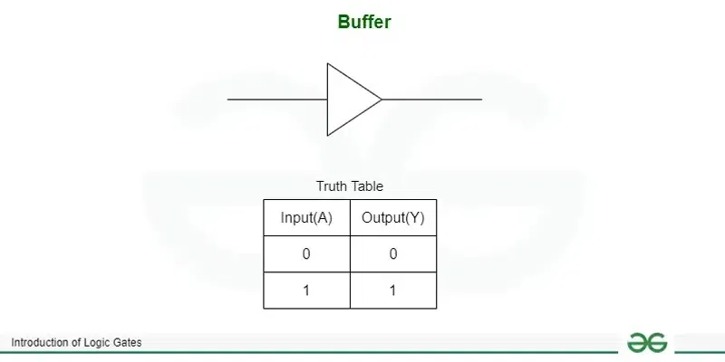
Buffer GATE
The Expression for Buffer can be given as
**Y=A
Where,
Y is the Output of gate
A is the input of gate
Every Logic gate has a graphical representation or symbol associated with it. Below is an image which shows the graphical symbols and truth tables associated with each logic gate. 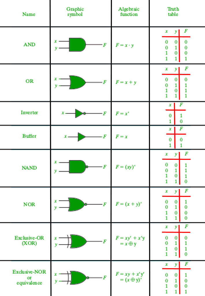
**Universal Logic Gates
Out of the eight logic gates discussed above, NAND and NOR are also known as **universal gates since they can be used to implement any digital circuit without using any other gate. This means that every gate can be created by NAND or NOR gates only. Implementation of three basic gates using NAND and NOR gates is shown below - 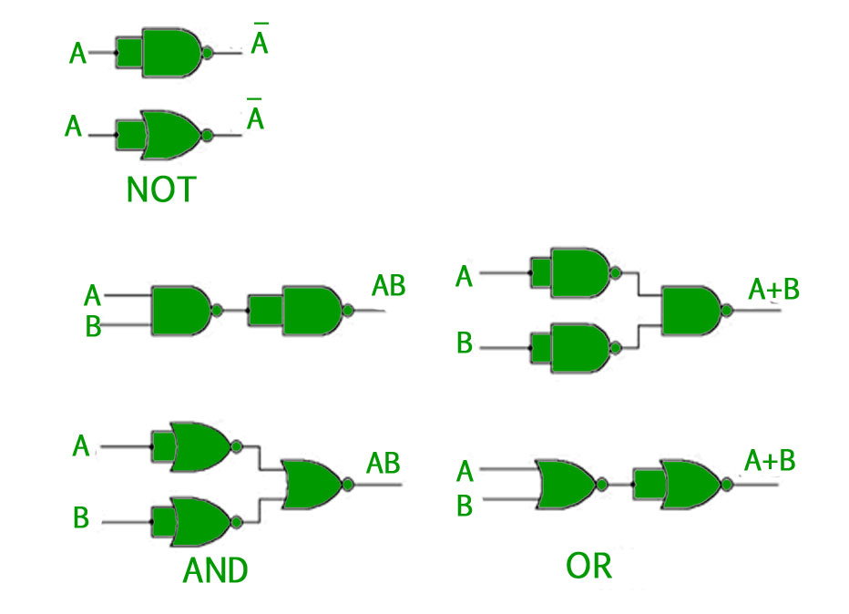
**Implemented Using NAND
The Implementation of NAND Gates are
- Implementation of AND Gate from NAND Gate
- I mplementation of NOR Gate from NAND Gate
- Implementation of OR Gate from NAND Gate
- Implementation of XOR Gate from NAND Gate
**Implemented using NOR
The Implementation of NOR Gate are
- Implementation of AND Gate from NOR Gate
- Implementation of OR Gate from NOR Gate
- Implementation of NOT Gate using NOR Gate
- Implementation of XOR Gate from NOR Gate
Applications of Logic Gates
Given Below are the Applications of logic gates
- Digital Circuits : The Logic gates are the building blocks in the digital circuits. They are used in designing various digital circuits multiplexer , Adder and etc.
- Arithmetic and Logic Units (ALUs): The ALUs are the important components in the CPUs which performs arithmetic and logical operations on binary data using combinations of logic gates.
- Memory Units: The Logic gate can be used to design memory units such as flip-flops and registers which can be used to store binary data.
- Digital Signal Processing (DSP): Logics gates are used in the DSP for operations such as filtering, modulation and etc. of digital signals.
Advantages of Logic Gates
- Basic Functions : Logic gates carry out basic logical functions like AND, OR, NOT, XOR, NAND, and NOR. All digital operations and dat respective processing rely on these functions.
- Versatility : Logic gates may be connected in different combinations to form complex circuits that could perform diverse tasks ranging from simple arithmetic to complicated decision making processes.
- Speed : Their extremely high speed rates make them an essential feature in today's information processing systems that aim for quickness in data analysis.
- Reliability : Being elements whose behaviors are accurately defined means there is no uncertainty about how they behave when used as part of a system.
- Scalability : Digital systems complexity increases by interconnecting and replicating these components without significant variations in size or complexity.
- Low Cost : Logic Gate costs are relatively low from production viewpoint thus making it popular among those who want to construct digital circuits inexpensively.
- Low Power Consumption : Power consumption is minimal with logic gates; hence less energy is needed for operating hence suitable for use with gadgets without batteries or devices running low power consumption applications at all times.
- Incorporating the merits of logic gates into their designs, engineers can come up with high-tech digital systems that make several technologies we use on a daily basis possible.
Di**sadvantages of Logic Gates :
Despite their numerous advantages, logic gates have their disadvantages. The following paragraphs discuss some shortcomings of logic gates.
- Complexity : The advancement and complexity of digital systems results in increasing number of logic gates and their interconnections, which causes designs that are very difficult to handle and troubleshoot.
- Pr opogation Delay : Small delay in the propagating signal is introduced with every logic gate. When several such gates are chained together, these delays can add up and have adverse effects on the overall speed and performance of the circuit.
- Noise Sensitivity : Even noise, interference, and interfering fields can make logic gates sensitive to errors in the output signal. Proper shielding and conditioning of signals at times are needed to reduce these effects.
- Power Dissipation : While logic gates are essentially low power, their dissipation can grow with the complexity of th e circuit. Heavy energy loss can generate thermal energy which necessitates supplementary cooling systems.
- Limited Functionality : Although it is possible to realize all sorts of logical operations with logic gates, there are usually restrictions on the types of functions that can be provided directly by a gate. The implementation of more complex functions may need several gates and extra circuitry.
- Design Constraints : While designing complex digital systems using logic gates, many issues have to be taken into consideration during the design process, like the integrity of the signals, timing constraints, and the power consumed. This may make this phase of design protracted and tricky.
- Cost of Implementation : Large-scale digital systems that include a large number of logic gates are very expensive in terms of the price of the components and the design and test procedures involved.
Conclusion
In this Article we have gone through Logic Gates, we have seen different types of logic gates with their logical diagrams and truth table, we have also gone through the implementation of Nor and Nand gate and we have seen the applications of the logical gates.