Getting Started with Verilog (original) (raw)
Last Updated : 23 Jul, 2025
For a long time, computer programming languages like FORTRAN, Pascal, and C were used to describe computer programs and their code execution is sequential. But there isn't any language to describe the digital circuits. This is when Hardware Description Language(HDL) came into play. HDLs are even popular for verification purposes. There are mainly two types of HDL:
- Verilog HDL
- VHDL (**Very High-Speed Integrated Circuit (VHSIC) **Hardware **Description **Language)
Note: Verilog HDL and VHDL aren't the same. VHDL was used before Verilog came into existence.
What is Verilog?
Verilog is a hardware description language that is used to realize the digital circuits through code. Verilog HDL is commonly used for design (RTL) and verification (Testbench Development) purposes for both Field programmable gate arrays (FPGA) and Application-specific Integrated Circuits (ASIC).
There are mainly three levels of abstraction (Different perspectives or views at which a design can be viewed or analyzed) for writing in Verilog:
- Gate Level Modeling
- Data-flow Modeling
- Behavioral Modeling
**Note: Before diving into the abstraction levels, let us first learn what is RTL.
**Register Transfer Level (RTL): Register transfer level is a low-level abstraction used in digital design to describe the behavior and functionality of a digital circuit or system. RTL is a general approach that describes digital circuits in terms of data flow at register level.
**Gate Level Modeling
If a circuit is represented completely using basic gates it is called gate level modeling. For example refer the below circuit of half adder where we can represent it simply using the AND and XOR gates.
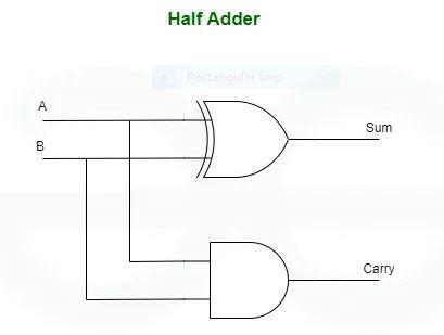
Half-Adder
This level of abstraction involves describing the circuit using primitive logic gates such as AND, OR, XOR, etc. This level provides a detailed representation of the circuit's structure and logic. Given Below is the RTL Code for Half Adder.
module half_adder(input a,b, output sum,carry);
xor x1(sum, a, b);
and a1(carry, a, b);
endmodule
**Data-Flow Modeling
In this level of abstraction we make use of the functions that define the working of the circuit instead of it's gate structure. This abstraction level mainly focuses on the flow of data through the circuit logic gates or functional expressions.
module half_adder(input a,b, output sum,carry); assign sum = a ^ b; assign carry = a & b; endmodule
**Behavioral Modeling
This is the highest level of abstraction in Verilog. At this level the designers describe the functionality of the circuit without specifying the functionality and structure of digital circuit. This modeling will be helpful because it focuses on what the circuit should do rather than how it should be implemented.
module half_adder(input a,b, output reg sum,carry); always@(*) begin sum = a ^ b; carry = a & b; endmodule
**Lexical Tokens
Lexical tokens are the basic building blocks of Verilog code that are keywords, identifiers, operators. They are like a way of communicating with the language and are useful for constructing Verilog statements and expressions. Some of the lexical tokens are:
- White space
- Comments
- Numbers
- Operators
- Identifiers and Keywords
- Datatypes
- Nets
- Registers
- Module declaration
**White Space
In Verilog, we use this white spaces in output commands like display,display, display,monitor, $strobe etc. In this "\t" represents tab space, "\n" represents new line.
There are 2 ways for writing comments in Verilog. One way is to enclose the comment in "/*........*/" . This will be helpful when there are multi-lined comments. and another way is to append "//" at the beginning of the sentence. This will be helpful for writing comments that are single-lined or of short context.
/* This is an example for Multi-lined comment. Hello there welcome to Verilog tutorial */ //this is a example for single line comment. //Hello there.
**Numbers
There are mainly 4 used number systems in Verilog. They are
- **Binary: b or B
- **Octal: o or O
- **Decimal: d or D
- **Hexadecimal: h or H
So numbers are represented in Verilog using the following format. '. In Verilog, it takes default size of 32 bits. If both the base and size are not mentioned it takes default of 32 bits and decimal number system notation.
For example: 4'b1100 is same as 4'd12 in decimal notation.
'b0111 is same as 00000000000000000000000000000111
123 by default is a 32 bit decimal number.
If any negative number is represented, by default it will be converted to 2's complement form.
Operators
There are mainly 3 types of operators, they are:
- **High-Speed
**Unary Operators
In this the operators like (+, -, ^, %, ~) appear to the left of the operand. For example,
x = ~y;
In this you can observe for the literal y, the operator is to the left of y.
**Binary Operators
In this, the operators appear in between the operands. For example:
X = Y ^ Z;
In this we can observe that the operator(^) is in between the operands Y and Z.
**Ternary/Conditional Operators
This Ternary operators are like a simple if else statements but they are written in a single line. They are represented in the format:
Conditional_expression ? True_expression : False_expression
For example,
X = (A && B && C) : 1'b1 : 1'b0;
Here if the expression evaluates (A && B && C) to 1 then the true expression i.e 1'b1 will be given as output else 1'b0 will be given as output.
Identifiers and Keywords
Identifier is the name given to a function, task or for a module in Verilog. These Identifiers must be in lowercase and they are case sensitive. Characters like Numbers, underscore, special characters like $ can be used for naming the identifier but they cannot be used as the first character of the identifier because they are reserved for some inbuilt function in Verilog.
For example identifier names like: my_identifier, my_identifier1, my_identifier$ can be used but identifiers like 1my_identifier, $my_identifier are illegal.
**Datatypes
There are 4 basic values in Verilog:
| **Value Level | Description |
|---|---|
| 0 | Logical Zero, False |
| 1 | Logical One, True |
| X | Unknown Value |
| Z | High impedance state |
The main intention of using a datatype in Verilog is to represent data storage elements like bits in a flip flop and transmission elements like wires that connect between logic gates, sequential and combinational circuits. There are mainly 2 types of data types in Verilog. They are
**1. Nets
Nets are continuously driven by the combinational logic circuits. It means it cannot store any values. It is represented by the keyword "wire" on the LHS. Default value of a net is 'Z' , which is a high impedance state.
wire a, b, y; assign y = a & b;
Here the variables are declared by the datatype of wire and for the variable y a keyword "assign" is used to drive the value of the RHS (a & b) to y.
**2. Regs
Point to be noted, Reg is different from hardware register. Declaring a Reg doesn't mean declaring a flip flop or a latch but it represents a storage element unlike net. A Reg is a datatype that we can use only through procedural statements.
reg a, b, y; always@(posedge clock) begin y = a & b; end
Module Declaration
Given Below is the Code for module declaration
module helper(a, b, y, z); input a, b; output y, z; y = a & b; z = a | b; endmodule
- In the above code, module signifies declaration of a module and helper signifies the name assigned to the module.
- The operands written in the brackets(a, b, y, z) are the input and output ports in the digital circuit. This port declaration can be empty also.
- In the code the ports a, b are declared as input ports and y, z are declared as output ports.
- Semicolon(";") in the code signifies the termination of a module statement.
- In the code y and z declaration represents the individual statements within the module.
- "endmodule" keyword represents the termination of a module.
Always Block in Verilog
Always block is a procedural block. It describes sequential circuits (latches, flip-flops) or combinational circuits. All always blocks are executed in parallel, But actually, they are executed in an order determined by the simulation tool. Signals assigned inside always block must be of type reg.
Sensitivity List
- It contains signals that affect outputs.
- In case of any change to the values of the signals in the sensitivity list, outputs must be reevaluated.
- It's specified by adding the @ symbol before the round brackets.
- The * symbol means adding all inputs to the sensitivity list. If the sensitivity list is not specified, it means that the always block will remain in execution.
Blocking VS Non-Blocking Assignment
| Blocking | Non-Blocking | |
|---|---|---|
| Symbol | = | <= |
| How it's executed | Executed Sequentially. Blocks next statements until it is executed.LHS is updated after reading RHS of the same statement. | Executed in Parallel.RHS is read immediately, but updating LHS starts after all reads are scheduled. |
| Purpose | Describe Multi-level Combinational Logic. | Describe Flip-flop assignment at the same time regardless to the order or the dependence. |
| If not triggered | If not triggered, it is uninitialized. | If not triggered, it keeps the last value. |
Don’t use both of them in the same always block.
**Different Classification of Verilog
- **Verilog-1995: Verilog-1995, also known as IEEE Standard 1364-1995, is the initial version of Verilog that introduced the language's basic syntax and features. It provides the fundamental constructs for describing digital circuits, including modules, ports, data types (wire, reg), and basic behavioral and structural modeling techniques.
- **Verilog-2001: Verilog-2001, an extension of Verilog-1995, introduced several new features and enhancements to the language to improve code readability, re-usability, and ease of design. It addressed some limitations of the previous version and introduced new constructs for better modeling and verification.
- **System Verilog: System Verilog is a significant extension of Verilog that adds new features and capabilities for both design and verification. It incorporates features from the Vera and Specman languages, providing a comprehensive solution for design, verification, and system-level modeling.
- **Verilog-AMS (Analog and Mixed-Signal): Verilog-AMS is an extension of Verilog that enables modeling of analog and mixed-signal systems alongside digital logic. It provides constructs for describing continuous-time analog behavior, such as voltage and current, in addition to digital signals and logic.
**Difference Between Verilog HDL and VHDL
Given Below is the Table for the difference between Verilog HDL and VHDL
| Verilog HDL | VHDL (Very High Speed Integrated Circuit HDL) |
|---|---|
| Easy syntax and resembles C language and less complex. | Complex Syntax and difficult to understand for a beginner. |
| Executes code in concurrent and sequential manner. | Executes code in concurrent and sequential manner. |
| Mostly used in defense and aerospace industries. | Mostly used in Semiconductor Industry. |
| Used in Safety and mission critical applications. | Used for ASIC and FPGA design. |
**Advantages of Verilog
- **Concise Syntax: Verilog has a straightforward syntax that allows for quick and efficient coding of digital circuits.
- **Industry Standard: It is widely used and accepted in the semiconductor industry, making it easier to collaborate with others and access resources.
- **Simulation and Synthesis: Verilog supports both simulation and synthesis, allowing designers to verify their designs and translate them into actual hardware.
- **Hierarchical Design: Verilog enables hierarchical design, which allows for the creation of complex systems by breaking them down into smaller, manageable modules.
**Disadvantages of Verilog
- **Steep Learning Curve: Verilog can be a bit difficult to understand for beginners due to syntax and concepts and takes time to get proficient.
- **Tool Dependency: Verilog design requires specialized tools for synthesis, simulation, and verification, which may come with associated costs and compatibility issues.
- **Version Compatibility: Compatibility issues may arise when using different versions of Verilog or when interfacing with third-party tools and libraries.
- **Verification Challenges: While Verilog supports simulation-based verification, establishing comprehensive test benches and ensuring complete coverage can be complex and time-consuming.
**Applications of Verilog
- **Embedded Systems: Verilog is used to design hardware components in embedded systems like microcontrollers and FPGAs.
- **Digital Signal Processing: Verilog enables the implementation of DSP algorithms in hardware for applications like audio and video processing.
- **Networking: Verilog is utilized in the design of networking hardware such as routers, switches, and network interface cards.
- **ASIC Design: Verilog is commonly employed in application-specific integrated circuit (ASIC) design for custom hardware implementations.
- **Autonomous Vehicles: Verilog finds applications in automotive electronics for systems like engine control units and advanced driver-assistance systems (ADAS).